ADC JESD Register Map
www.ti.com
434
SBAU337–May 2020
Submit Documentation Feedback
Copyright © 2020, Texas Instruments Incorporated
Serial Interface Register Maps
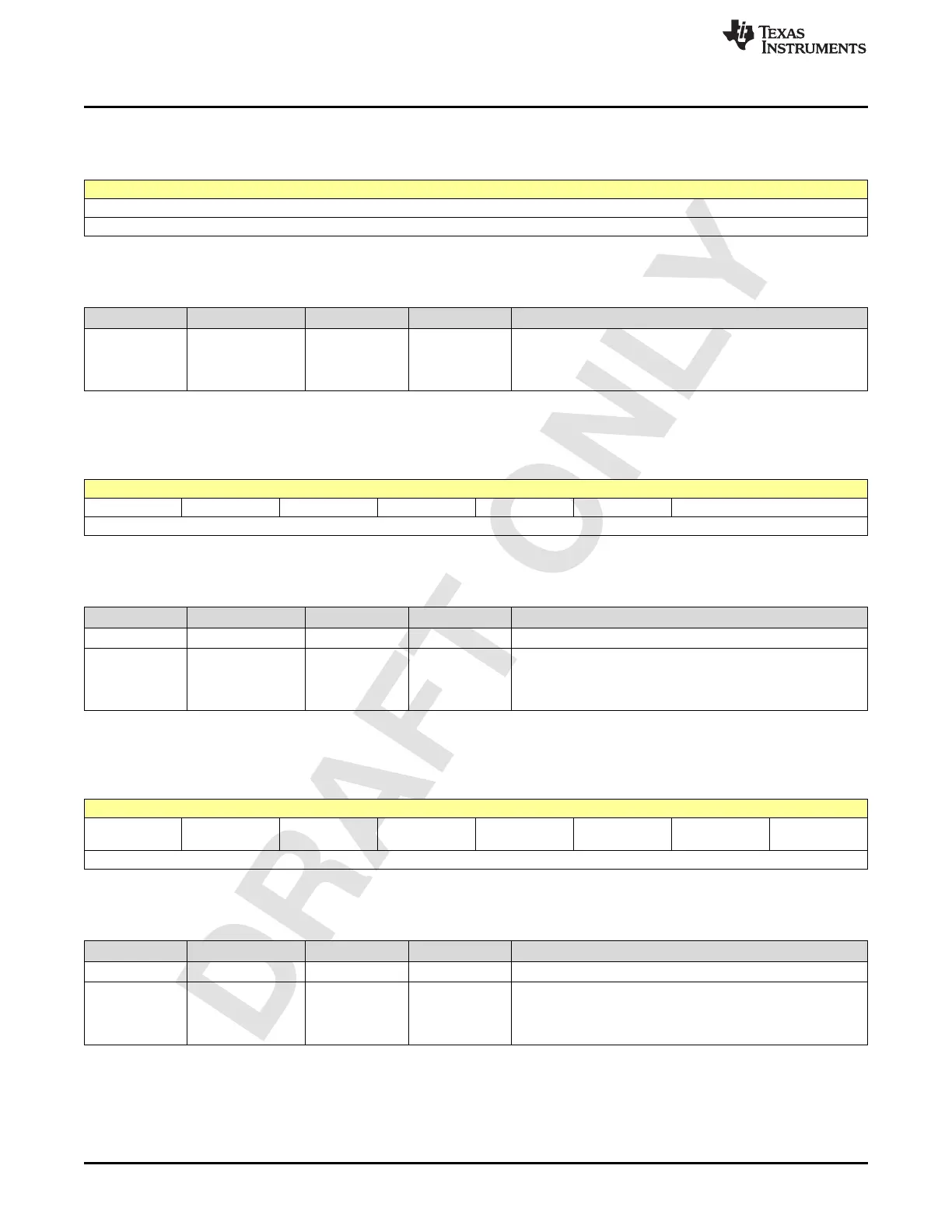
2.5.141 Register CDh (offset = CDh) [reset = 0h]
Figure 2-637. Register CDh
7 6 5 4 3 2 1 0
JESDC_CMD[15:8]
R/W-0h
LEGEND: R/W = Read/Write; W = Write only; -n = value after reset
Table 2-642. Register CD Field Descriptions
Bit Field Type Reset Description
7-0 JESDC_CMD[15:8] R/W 0h
For JESD-C
6 bits corresponding to 6 command bits used in CRC and FEC
encoding.
All 18 bits are used in CMD encoding is used
2.5.142 Register CEh (offset = CEh) [reset = 0h]
Figure 2-638. Register CEh
7 6 5 4 3 2 1 0
0 0 0 0 0 0 JESDC_CMD[17:16]
R/W-0h R/W-0h R/W-0h R/W-0h R/W-0h R/W-0h R/W-0h
LEGEND: R/W = Read/Write; W = Write only; -n = value after reset
Table 2-643. Register CE Field Descriptions
Bit Field Type Reset Description
7-2 0 R/W 0h Must read or write 0
1-0
JESDC_CMD[17:1
6]
R/W 0h
For JESD-C
6 bits corresponding to 6 command bits used in CRC and FEC
encoding.
All 18 bits are used in CMD encoding is used
2.5.143 Register CFh (offset = CFh) [reset = 0h]
Figure 2-639. Register CFh
7 6 5 4 3 2 1 0
0 0 0 0 0 0 0 FEC_MASK_E
N
R/W-0h R/W-0h R/W-0h R/W-0h R/W-0h R/W-0h R/W-0h R/W-0h
LEGEND: R/W = Read/Write; W = Write only; -n = value after reset
Table 2-644. Register CF Field Descriptions
Bit Field Type Reset Description
7-1 0 R/W 0h Must read or write 0
0-0 FEC_MASK_EN R/W 0h
When 1, 26 ones are sent in the place of FEC header. This
can be used during initial link up, so that the receiver can align
to the correct multi-block end quickly. Once locked the
receiver needs to clear this bit.

 Loading...

