www.ti.com
RX Top Register Map
851
SBAU337–May 2020
Submit Documentation Feedback
Copyright © 2020, Texas Instruments Incorporated
Serial Interface Register Maps
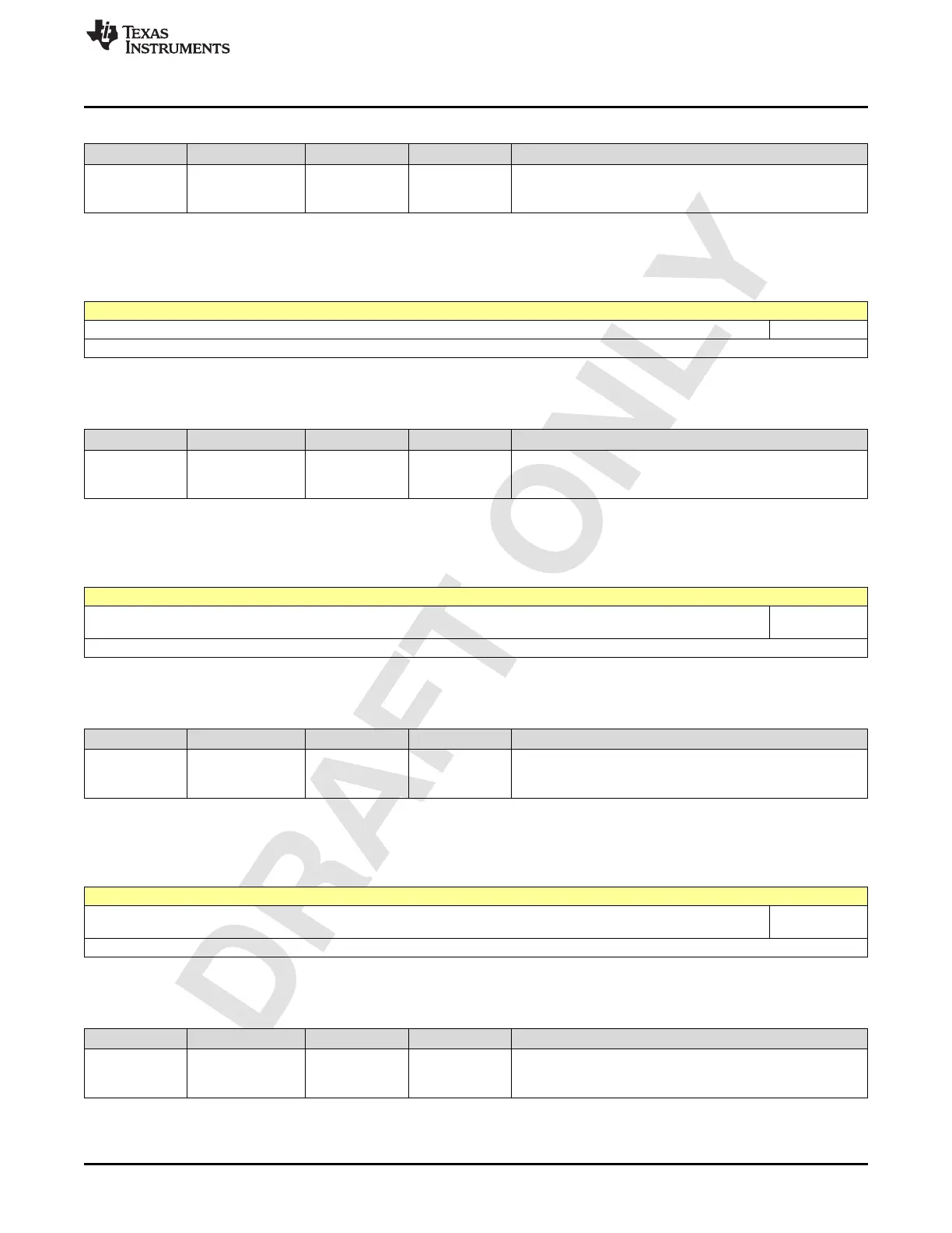
Table 2-1892. Register 740 Field Descriptions
Bit Field Type Reset Description
0-0
RX_DDC_ROOT_
CLOCK_GATE
R/W 1h
Gate/ungate the root clock to the RX digital.
0: Ungate
1: Gate
2.13.468 Register 770h (offset = 770h) [reset = 0h]
Figure 2-1880. Register 770h
7 6 5 4 3 2 1 0
RX_DDC_PDN
R/W-0h
LEGEND: R/W = Read/Write; W = Write only; -n = value after reset
Table 2-1893. Register 770 Field Descriptions
Bit Field Type Reset Description
0-0 RX_DDC_PDN R/W 0h
Power down the complete RX channel
1 : Power down the entire RX channel
0 : Normal mode of operation
2.13.469 Register 771h (offset = 771h) [reset = 0h]
Figure 2-1881. Register 771h
7 6 5 4 3 2 1 0
RX_DDC_PRE
_DECIM_PDN
R/W-0h
LEGEND: R/W = Read/Write; W = Write only; -n = value after reset
Table 2-1894. Register 771 Field Descriptions
Bit Field Type Reset Description
0-0
RX_DDC_PRE_DE
CIM_PDN
R/W 0h
Power down the pre-decimation section of RX channel
1 : Power down the Pre DDC blocks of the RX channel
0 : Normal mode of operation
2.13.470 Register 772h (offset = 772h) [reset = 0h]
Figure 2-1882. Register 772h
7 6 5 4 3 2 1 0
RX_DDC_DECI
M_PDN
R/W-0h
LEGEND: R/W = Read/Write; W = Write only; -n = value after reset
Table 2-1895. Register 772 Field Descriptions
Bit Field Type Reset Description
0-0
RX_DDC_DECIM_
PDN
R/W 0h
Power down the DDC section of RX channel
1 : Power down the Dec Chain blocks of the RX channel
0 : Normal mode of operation

 Loading...

