www.ti.com
DSA Page 0 Register Map
591
SBAU337–May 2020
Submit Documentation Feedback
Copyright © 2020, Texas Instruments Incorporated
Serial Interface Register Maps
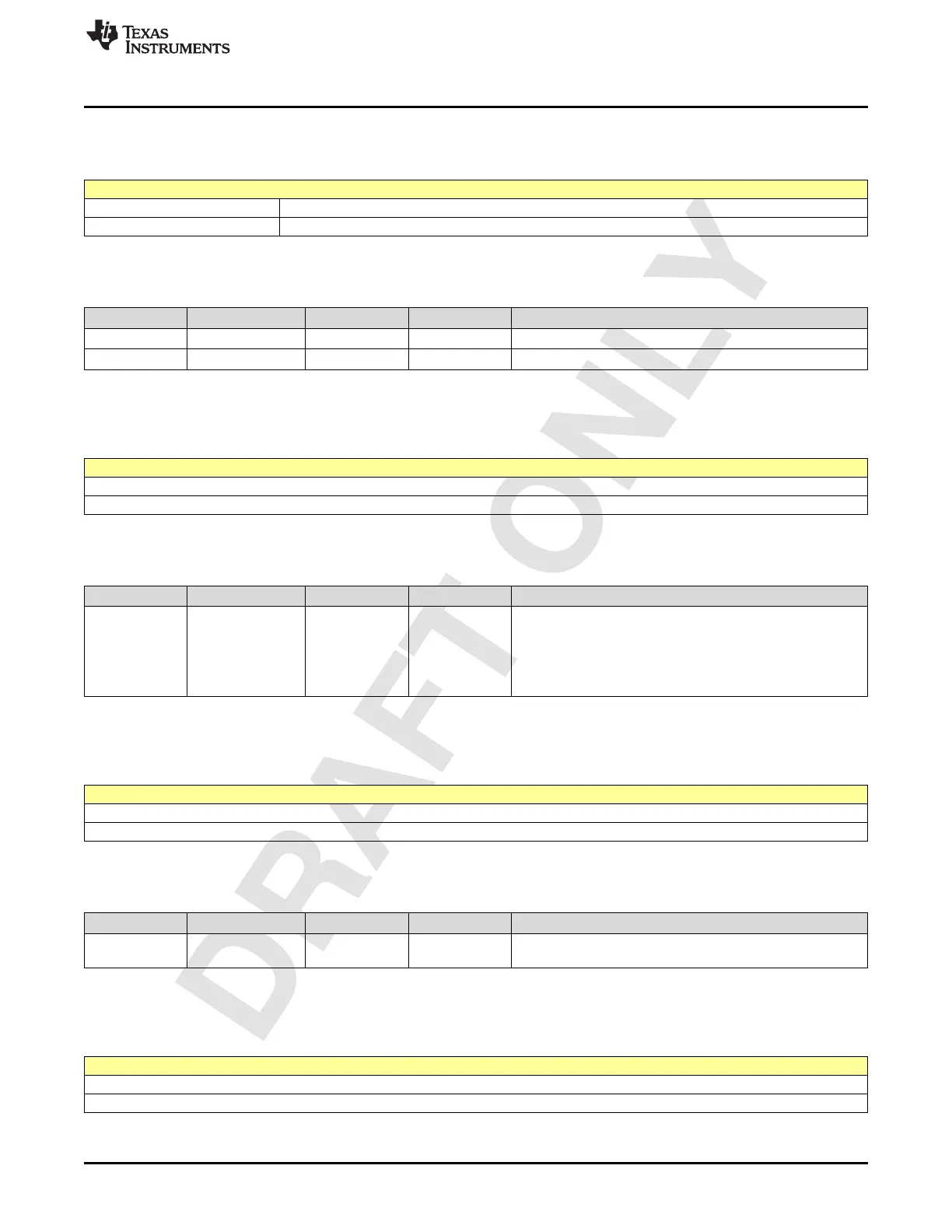
2.9.10 Register CCh (offset = CCh) [reset = 0h]
Figure 2-1102. Register CCh
7 6 5 4 3 2 1 0
TXB_DSA_FINE TXB_DSA_INDEX
R/W-0h R/W-0h
LEGEND: R/W = Read/Write; W = Write only; -n = value after reset
Table 2-1111. Register CC Field Descriptions
Bit Field Type Reset Description
7-6 TXB_DSA_FINE R/W 0h fine code for txb.
5-0 TXB_DSA_INDEX R/W 0h Similar to txa_dsa_index applies to txb channel.
2.9.11 Register D0h (offset = D0h) [reset = 18h]
Figure 2-1103. Register D0h
7 6 5 4 3 2 1 0
TXA_DSA_DIG0_GAIN
R/W-18h
LEGEND: R/W = Read/Write; W = Write only; -n = value after reset
Table 2-1112. Register D0 Field Descriptions
Bit Field Type Reset Description
7-0
TXA_DSA_DIG0_G
AIN
R/W 18h
DIg gain0 is for band0. There is a mask for these registers as
well. By choosing the mask only any desired trigger for CP
can be created.
Normally the mask may be programmed so that only ana
index trigger the CP/dsa change.
mask is present in SpiA page.
2.9.12 Register D4h (offset = D4h) [reset = 18h]
Figure 2-1104. Register D4h
7 6 5 4 3 2 1 0
TXB_DSA_DIG0_GAIN
R/W-18h
LEGEND: R/W = Read/Write; W = Write only; -n = value after reset
Table 2-1113. Register D4 Field Descriptions
Bit Field Type Reset Description
7-0
TXB_DSA_DIG0_G
AIN
R/W 18h For txb.
2.9.13 Register D8h (offset = D8h) [reset = 18h]
Figure 2-1105. Register D8h
7 6 5 4 3 2 1 0
TXA_DSA_DIG1_GAIN
R/W-18h
LEGEND: R/W = Read/Write; W = Write only; -n = value after reset