RX Top Register Map
www.ti.com
836
SBAU337–May 2020
Submit Documentation Feedback
Copyright © 2020, Texas Instruments Incorporated
Serial Interface Register Maps
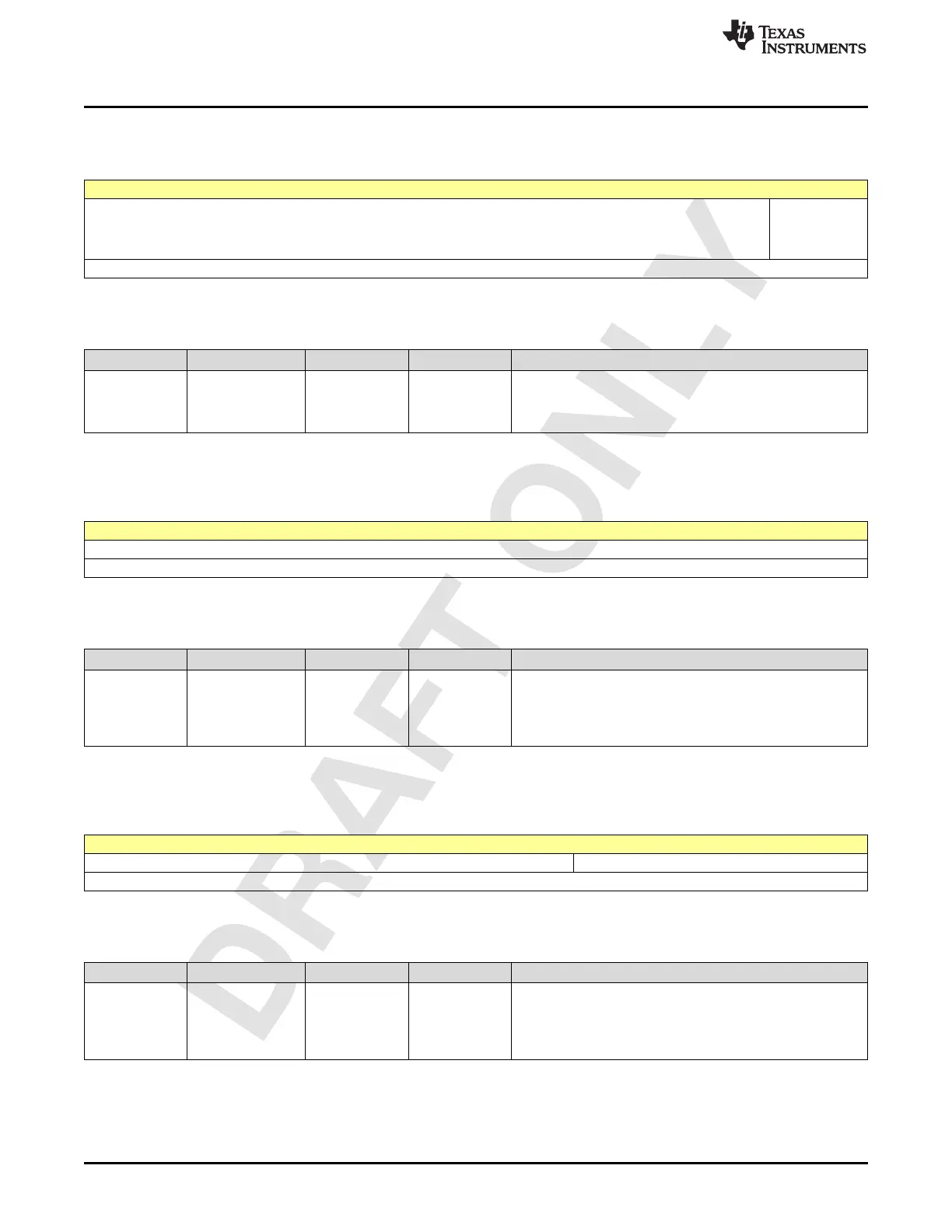
2.13.424 Register 5BCh (offset = 5BCh) [reset = 0h]
Figure 2-1836. Register 5BCh
7 6 5 4 3 2 1 0
RX_AGC_ENA
BLE_GPIO_RE
SET_FEATUR
E
R/W-0h
LEGEND: R/W = Read/Write; W = Write only; -n = value after reset
Table 2-1849. Register 5BC Field Descriptions
Bit Field Type Reset Description
0-0
RX_AGC_ENABLE
_GPIO_RESET_FE
ATURE
R/W 0h
Enables Control of peak detector reset using GPIO. Used in
only External AGC Mode.
0 : Disable
1 : Enable
2.13.425 Register 5C0h (offset = 5C0h) [reset = 5h]
Figure 2-1837. Register 5C0h
7 6 5 4 3 2 1 0
RX_AGC_CLK_DIV_FACTOR_DVGA_CTRL[7:0]
R/W-5h
LEGEND: R/W = Read/Write; W = Write only; -n = value after reset
Table 2-1850. Register 5C0 Field Descriptions
Bit Field Type Reset Description
7-0
RX_AGC_CLK_DI
V_FACTOR_DVGA
_CTRL[7:0]
R/W 5h
Clock divide factor for external DVGA control module.
This factor is used to derive the SPI clock when the device is
acting as a master to control external dvga settings. Should be
programmed such that the output clock is <25 MHz.
dvga_spi_clock = Fs/8/(clk_div_factor_dvga_ctrl+1)
2.13.426 Register 5C1h (offset = 5C1h) [reset = 0h]
Figure 2-1838. Register 5C1h
7 6 5 4 3 2 1 0
RX_AGC_CLK_DIV_FACTOR_DVGA_CTRL[10:8]
R/W-0h
LEGEND: R/W = Read/Write; W = Write only; -n = value after reset
Table 2-1851. Register 5C1 Field Descriptions
Bit Field Type Reset Description
2-0
RX_AGC_CLK_DI
V_FACTOR_DVGA
_CTRL[10:8]
R/W 0h
Clock divide factor for external DVGA control module.
This factor is used to derive the SPI clock when the device is
acting as a master to control external dvga settings. Should be
programmed such that the output clock is <25 MHz.
dvga_spi_clock = Fs/8/(clk_div_factor_dvga_ctrl+1)

 Loading...

