List of Macros
www.ti.com
126
SBAU337–May 2020
Submit Documentation Feedback
Copyright © 2020, Texas Instruments Incorporated
Macro
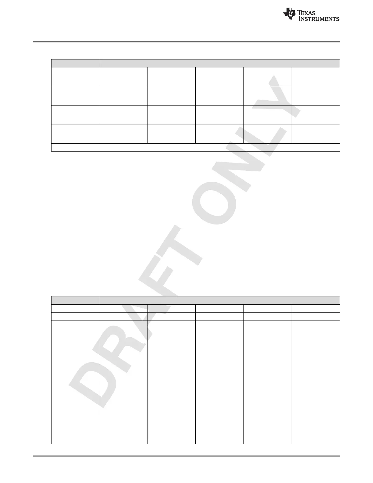
Table 1-74. (continued)
Macro AGC Gain Step Size Configuration
2 0x01 1 Big Step Attack
Step Size (1 LSB =
0.5 dB)
3 0x02 1 Small Step Attack
Step Size (1 LSB =
0.5 dB)
4 0x03 1 Big Step Decay
Step Size (1 LSB =
0.5 dB)
5 0x04 1 Small Step Decay
Step Size( 1 LSB =
0.5 dB)
Memory Not used
Step Size: Whenever some detector triggers, this step size mentions the DSA change that needs to
happen in the appropriate direction. These values are in dB scale and each value is a 6 bit number. The
value should not cross the maximum DSA attenuation configured. For the attack detectors, the DSA
attenuation will increase. For the decay detectors, the DSA attenuation will decrease. The different types
of step sizes that are present are mentioned here:
1. Big Step Attack Step Size
2. Small Step Attack Step Size
3. Big Step Decay Step Size and
4. Small Step Decay Step Size
As the names suggest, the big step attack or decay step size is expected to be larger than the small step
attack and decay step size.
1.2.5.16 AGC State Control Macro
This is the main macro which actually starts the entire AGC action. After configuring all the required AGC
settings, this macro needs to be initiated.
Table 1-75.
Macro AGC State Control
Opcode 0x68
Operand Offset Length Value Functionality Results
1 0x00 1 RX Channel Select Bit 0: 1 → Value
specified in
subsequent
operands is valid for
1RX.
Bit 1: 1 → Value
specified in
subsequent
operands is valid for
2RX.
Bit 2: 1 → Value
specified in
subsequent
operands is valid for
3RX.
Bit 3: 1 → Value
specified in
subsequent
operands is valid for
4RX.
Bit 4 → RESERVED
Bit 5 → RESERVED
 Loading...


