Example Macro Call Sequence
www.ti.com
138
SBAU337–May 2020
Submit Documentation Feedback
Copyright © 2020, Texas Instruments Incorporated
Macro
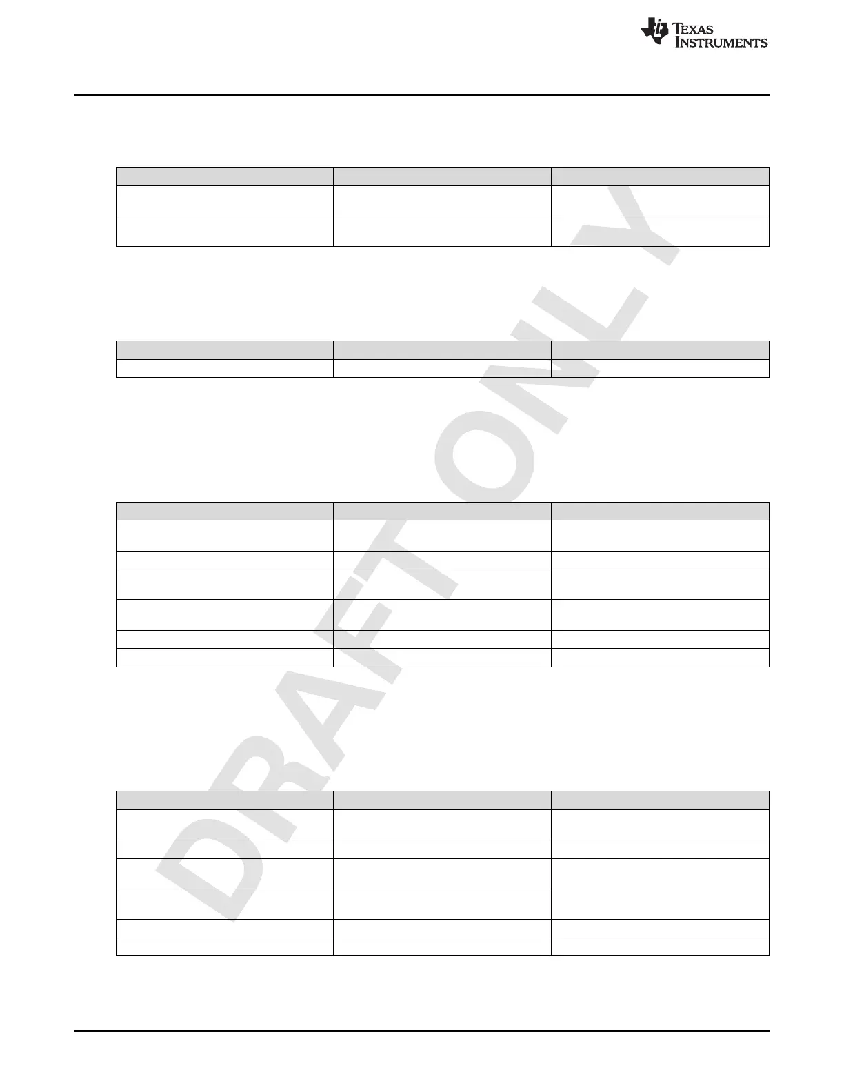
1.4.10 TX DAC Rate Configuration (Opcode – 0x2E)
Table 1-96.
Operand Value Comments
1 0x03 Configure Common Setting for both pairs
of TX Channels
2 0x11 Select DAC Sampling Rate of
11796.48MHz
1.4.11 Channel Frequency Resolution (Opcode – 0x2F)
Table 1-97.
Operand Value Comments
1 0x00 ‘kHz’ Frequency Resolution Mode
1.4.12 RX Channel Frequency Configuration (Opcode – 0x31)
Band 1 of RX Channels is configured to receive signal centered at 3500 MHz. Band 2 of RX Channels is
configured to receive signal centered at 4000 MHz.
Table 1-98.
Operand Value Comments
1 0x0F Configure Common Channel Frequency
for all RX
2 0x00 Single NCO Mode
3 0x000867E0 Band 1 frequency of 3500MHz modulo
RX-ADC-Rate.
3 0x00100900 Band 2 frequency of 4000MHz modulo
RX-ADC-Rate.
4 0x0 Unused
5 0x0 Unused
1.4.13 FB Channel Frequency Configuration (Opcode – 0x32)
It is assumed here that FB channels are configured in dual NCO mode, with the first NCO being used to
receive TX Band 1 transmission and the second NCO for TX Band 2 transmission.
Table 1-99.
Operand Value Comments
1 0x03 Configure Common Channel Frequency
for all FB
2 0x01 Dual NCO Mode
3 0x000867E0 TX Band 1 frequency of 3500MHz modulo
FB-ADC-Rate.
3 0x00100900 TX Band 2 frequency of 4000MHz modulo
FB-ADC-Rate.
4 0x00000000 Unused
5 0x00000000 Unused

 Loading...

