SERDES Register Map
www.ti.com
468
SBAU337–May 2020
Submit Documentation Feedback
Copyright © 2020, Texas Instruments Incorporated
Serial Interface Register Maps
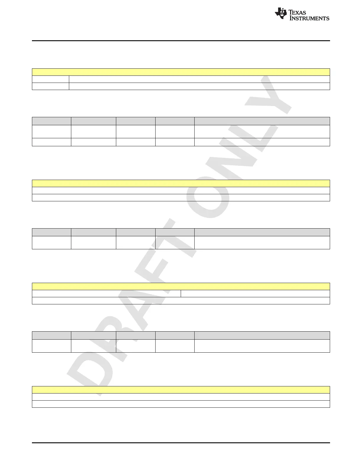
2.6.2 Register 4001h (offset = 4001h) [reset = 10h]
Figure 2-716. Register 4001h
7 6 5 4 3 2 1 0
LANE_RESET DFE_INIT_1
R/W-0h R/W-10h
LEGEND: R/W = Read/Write; W = Write only; -n = value after reset
Table 2-722. Register 4001 Field Descriptions
Bit Field Type Reset Description
7-7 LANE_RESET R/W 0h
State machine reset level trigger
1h Reset
6-0 DFE_INIT_1 R/W 10h The initialization value1 for DFE in S7.6 format
2.6.3 Register 4002h (offset = 4002h) [reset = 8h]
Figure 2-717. Register 4002h
7 6 5 4 3 2 1 0
CNTR_TARGET_DEPTH[7:0]
R/W-8h
LEGEND: R/W = Read/Write; W = Write only; -n = value after reset
Table 2-723. Register 4002 Field Descriptions
Bit Field Type Reset Description
7-0
CNTR_TARGET_D
EPTH[7:0]
R/W 8h The smaller this value, the deeper the eye target.
2.6.4 Register 4003h (offset = 4003h) [reset = 0h]
Figure 2-718. Register 4003h
7 6 5 4 3 2 1 0
CNTR_TARGET_DEPTH[11:8]
R/W-0h
LEGEND: R/W = Read/Write; W = Write only; -n = value after reset
Table 2-724. Register 4003 Field Descriptions
Bit Field Type Reset Description
3-0
CNTR_TARGET_D
EPTH[11:8]
R/W 0h The smaller this value, the deeper the eye target.
2.6.5 Register 4004h (offset = 4004h) [reset = 20h]
Figure 2-719. Register 4004h
7 6 5 4 3 2 1 0
CNTR_TARGET_PAT[7:0]
R/W-20h
LEGEND: R/W = Read/Write; W = Write only; -n = value after reset

 Loading...

