www.ti.com
SERDES Register Map
481
SBAU337–May 2020
Submit Documentation Feedback
Copyright © 2020, Texas Instruments Incorporated
Serial Interface Register Maps
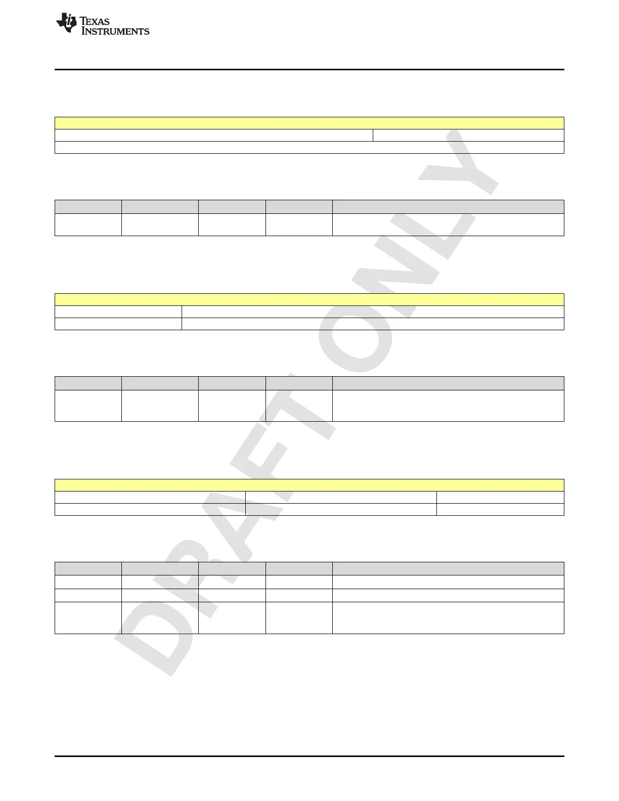
2.6.47 Register 407Dh (offset = 407Dh) [reset = 0h]
Figure 2-761. Register 407Dh
7 6 5 4 3 2 1 0
LINK_INIT_VAL_4[10:8]
R/W-0h
LEGEND: R/W = Read/Write; W = Write only; -n = value after reset
Table 2-767. Register 407D Field Descriptions
Bit Field Type Reset Description
2-0
LINK_INIT_VAL_4[
10:8]
R/W 0h Initial parameter set values 4. Used during link-up.
2.6.48 Register 4082h (offset = 4082h) [reset = C0h]
Figure 2-762. Register 4082h
7 6 5 4 3 2 1 0
TIMING_UPDN_MOD_EN[1:0]
R/W-3h
LEGEND: R/W = Read/Write; W = Write only; -n = value after reset
Table 2-768. Register 4082 Field Descriptions
Bit Field Type Reset Description
7-6
TIMING_UPDN_M
OD_EN[1:0]
R/W 3h
Timing up/down mode enable:
0h: Disable
1h Enable
2.6.49 Register 4083h (offset = 4083h) [reset = FFh]
Figure 2-763. Register 4083h
7 6 5 4 3 2 1 0
TUD_UP_RATIO TUD_DN_RATIO TIMING_UPDN_MOD_EN[3:2]
R/W-7h R/W-7h R/W-3h
LEGEND: R/W = Read/Write; W = Write only; -n = value after reset
Table 2-769. Register 4083 Field Descriptions
Bit Field Type Reset Description
7-5 TUD_UP_RATIO R/W 7h Timing Loop UP direction control ratio.
4-2 TUD_DN_RATIO R/W 7h Timing Loop DOWN direction control ratio.
1-0
TIMING_UPDN_M
OD_EN[3:2]
R/W 3h
Timing up/down mode enable:
0h: Disable
1h Enable