www.ti.com
DAC JESD Register Map
267
SBAU337–May 2020
Submit Documentation Feedback
Copyright © 2020, Texas Instruments Incorporated
Serial Interface Register Maps
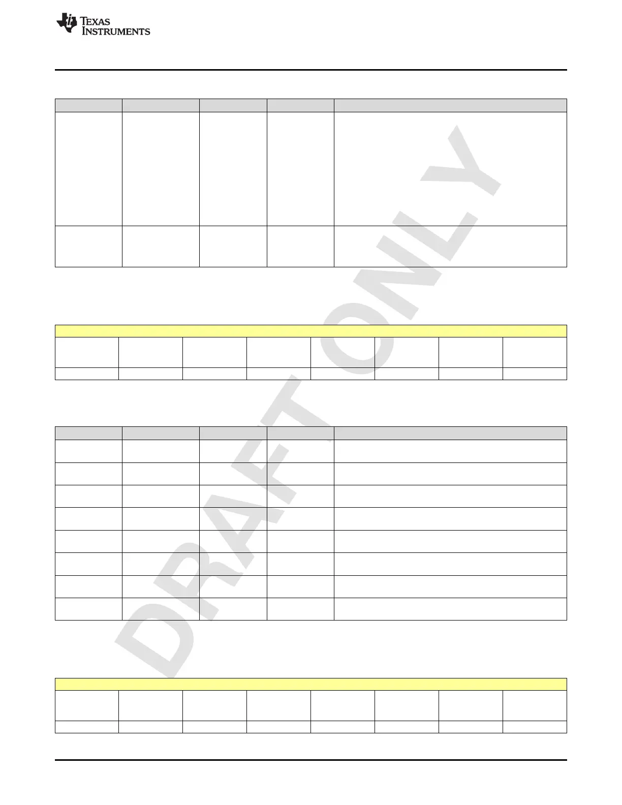
Table 2-240. Register 26 Field Descriptions (continued)
Bit Field Type Reset Description
3-2 NUM_LINKS R/W 1h
Number of links in a 4T/2T instance.
0 : 1 link/8 Lanes : link0. Supported M=2,4,8,16.
1 : 1 link/4 Lanes : link0-lanes[0:3]: Supported M=2,4,8,16.
link1-lanes[4:7]: Supported M=2,4,8,16.
2 : 1 link/2 Lanes : link0-lanes[0:1], link1-lanes[2:3],link2-
lanes[4:5],link3-lanes[6:7], Supported M=2,4,8.
3 : 1 link/2 Lanes : link0-lanes[0:1], link1-lanes[2:3],link2-
lanes[4:5],link3-lanes[6:7], Supported M=2,4.
0 : 1 link/8 Lanes
1 : 1 link/4 Lanes
2 : 1 link/2 Lanes
3 : 1 link/2 Lanes
1-0 JESD_STD_SEL R/W 0h
JESD standard select
0 : JESDB
1 : unused
2 : JESDC
2.4.8 Register 27h (offset = 27h) [reset = 0h]
Figure 2-237. Register 27h
7 6 5 4 3 2 1 0
MAPPER_SYN
C_FIFO_TX4_2
_EN
MAPPER_SYN
C_FIFO_TX4_1
_EN
MAPPER_SYN
C_FIFO_TX3_2
_EN
MAPPER_SYN
C_FIFO_TX3_1
_EN
MAPPER_SYN
C_FIFO_TX2_2
_EN
MAPPER_SYN
C_FIFO_TX2_1
_EN
MAPPER_SYN
C_FIFO_TX1_2
_EN
MAPPER_SYN
C_FIFO_TX1_1
_EN
R/W-0h R/W-0h R/W-0h R/W-0h R/W-0h R/W-0h R/W-0h R/W-0h
LEGEND: R/W = Read/Write; W = Write only; -n = value after reset
Table 2-241. Register 27 Field Descriptions
Bit Field Type Reset Description
7-7
MAPPER_SYNC_F
IFO_TX4_2_EN
R/W 0h TESTMODE
6-6
MAPPER_SYNC_F
IFO_TX4_1_EN
R/W 0h TESTMODE
5-5
MAPPER_SYNC_F
IFO_TX3_2_EN
R/W 0h TESTMODE
4-4
MAPPER_SYNC_F
IFO_TX3_1_EN
R/W 0h TESTMODE
3-3
MAPPER_SYNC_F
IFO_TX2_2_EN
R/W 0h TESTMODE
2-2
MAPPER_SYNC_F
IFO_TX2_1_EN
R/W 0h TESTMODE
1-1
MAPPER_SYNC_F
IFO_TX1_2_EN
R/W 0h TESTMODE
0-0
MAPPER_SYNC_F
IFO_TX1_1_EN
R/W 0h TESTMODE
2.4.9 Register 28h (offset = 28h) [reset = 0h]
Figure 2-238. Register 28h
7 6 5 4 3 2 1 0
MAPPER_SYN
C_FIFO_TX4_
MODE_OVR
MAPPER_SYN
C_FIFO_TX3_
MODE_OVR
MAPPER_SYN
C_FIFO_TX2_
MODE_OVR
MAPPER_SYN
C_FIFO_TX1_
MODE_OVR
MAPPER_SYN
C_FIFO_TX4_
OFFSET_OVR
MAPPER_SYN
C_FIFO_TX3_
OFFSET_OVR
MAPPER_SYN
C_FIFO_TX2_
OFFSET_OVR
MAPPER_SYN
C_FIFO_TX1_
OFFSET_OVR
R/W-0h R/W-0h R/W-0h R/W-0h R/W-0h R/W-0h R/W-0h R/W-0h
LEGEND: R/W = Read/Write; W = Write only; -n = value after reset

 Loading...

