www.ti.com
DAC JESD Register Map
361
SBAU337–May 2020
Submit Documentation Feedback
Copyright © 2020, Texas Instruments Incorporated
Serial Interface Register Maps
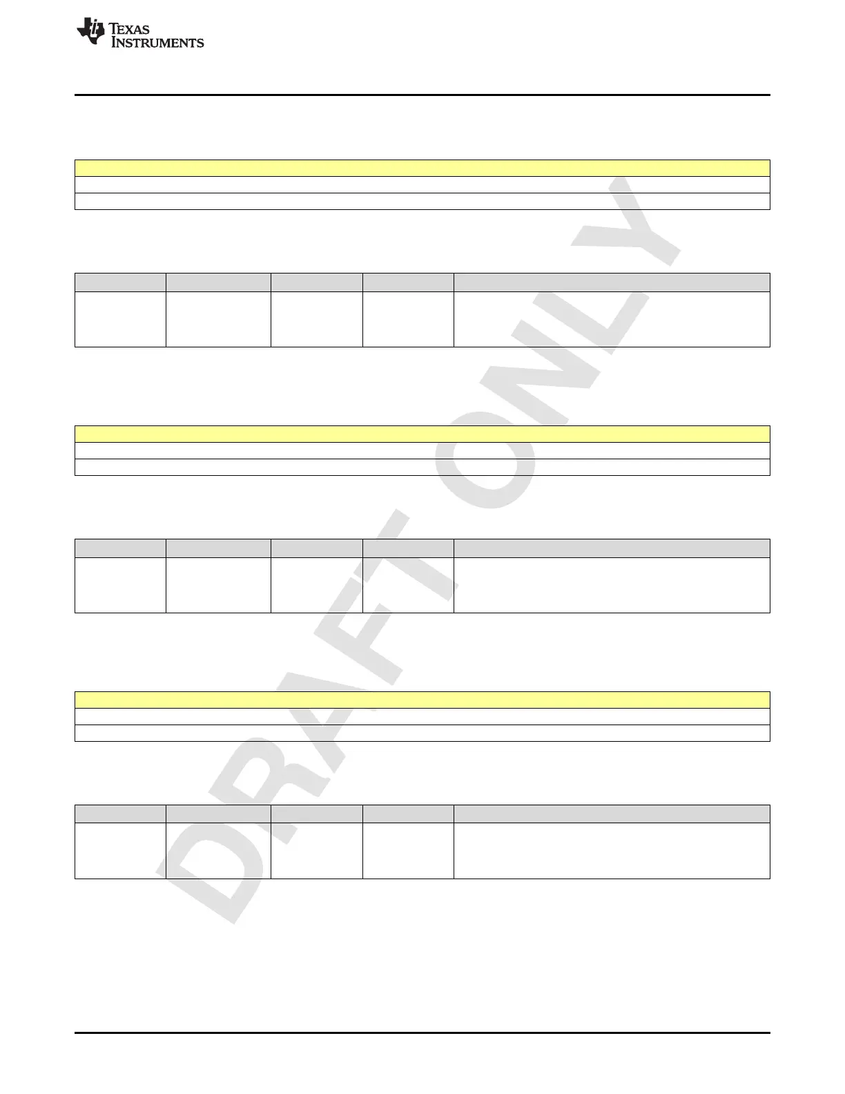
2.4.244 Register 138h (offset = 138h) [reset = 0h]
Figure 2-473. Register 138h
7 6 5 4 3 2 1 0
LINK0_SYNC_RELEASE_RBD_M1[7:0]
R/W-0h
LEGEND: R/W = Read/Write; W = Write only; -n = value after reset
Table 2-477. Register 138 Field Descriptions
Bit Field Type Reset Description
7-0
LINK0_SYNC_REL
EASE_RBD_M1[7:
0]
R/W 0h
For lanes[0:1]/[4:5], By default in JESDB, syncz assertion
happens on a multiframe-end. We can use this register along
with the rbd_counter to time the syncz assertion. TO enable
this feature, we need to set lane_test_mode[1] to 1
2.4.245 Register 139h (offset = 139h) [reset = 0h]
Figure 2-474. Register 139h
7 6 5 4 3 2 1 0
LINK0_SYNC_RELEASE_RBD_M1[15:8]
R/W-0h
LEGEND: R/W = Read/Write; W = Write only; -n = value after reset
Table 2-478. Register 139 Field Descriptions
Bit Field Type Reset Description
7-0
LINK0_SYNC_REL
EASE_RBD_M1[15
:8]
R/W 0h
For lanes[0:1]/[4:5], By default in JESDB, syncz assertion
happens on a multiframe-end. We can use this register along
with the rbd_counter to time the syncz assertion. TO enable
this feature, we need to set lane_test_mode[1] to 1
2.4.246 Register 13Ah (offset = 13Ah) [reset = 0h]
Figure 2-475. Register 13Ah
7 6 5 4 3 2 1 0
LINK1_SYNC_RELEASE_RBD_M1[7:0]
R/W-0h
LEGEND: R/W = Read/Write; W = Write only; -n = value after reset
Table 2-479. Register 13A Field Descriptions
Bit Field Type Reset Description
7-0
LINK1_SYNC_REL
EASE_RBD_M1[7:
0]
R/W 0h
For lanes[2:3]/[6:7], By default in JESDB, syncz assertion
happens on a multiframe-end. We can use this register along
with the rbd_counter to time the syncz assertion. TO enable
this feature, we need to set lane_test_mode[1] to 1

 Loading...

