Peripherals Routed Through the DAI
A-214 ADSP-214xx SHARC Processor Hardware Reference
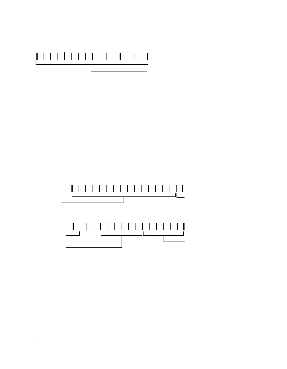
Clock Register (RTC_CLOCK)
This register, shown in Figure A-113, is used to read or write the current
time. It has no reset and an undefined value when the module is first pow-
ered up. This register is updated every second. If RTC is already running
when the core starts up, the values read from
RTC_CLOCK are zero until the
first second event occurs. In this case, programs must wait for the second
event and then read the register. Writes of invalid time values are
forbidden.
Alarm Register (RTC_ALARM)
This register, shown in Figure A-114, is programmed by software for the
time (in hours, minutes, and seconds) the alarm interrupt occurs. Reads
and writes can occur at any time. The alarm interrupt occurs whenever the
hour, minute, and second fields first match those of the RTC status
Figure A-112. RTC_SWTCH Register (RW)
Figure A-113. RTC_CLOCK Register (RW)
09 837564 2114 12 11 101315
STOP_WATCH
Stop Watch Counter
Value
09 837564 2114 12 11 101315
31 302928 27 26 25 24 23 22 21 20 19 18 17 16
HOUR (16-12)
MINUTE (11-6)
Hour Count 0–23
Minute Count 0–59
DAY (31-17)
Day Count 0–32767
SECOND (5-0)
Second Count 0–59
HOUR (16-12) (Con’t)
Hour Count 0–23

 Loading...

