SRU Programming
13-4 ADSP-214xx SHARC Processor Hardware Reference
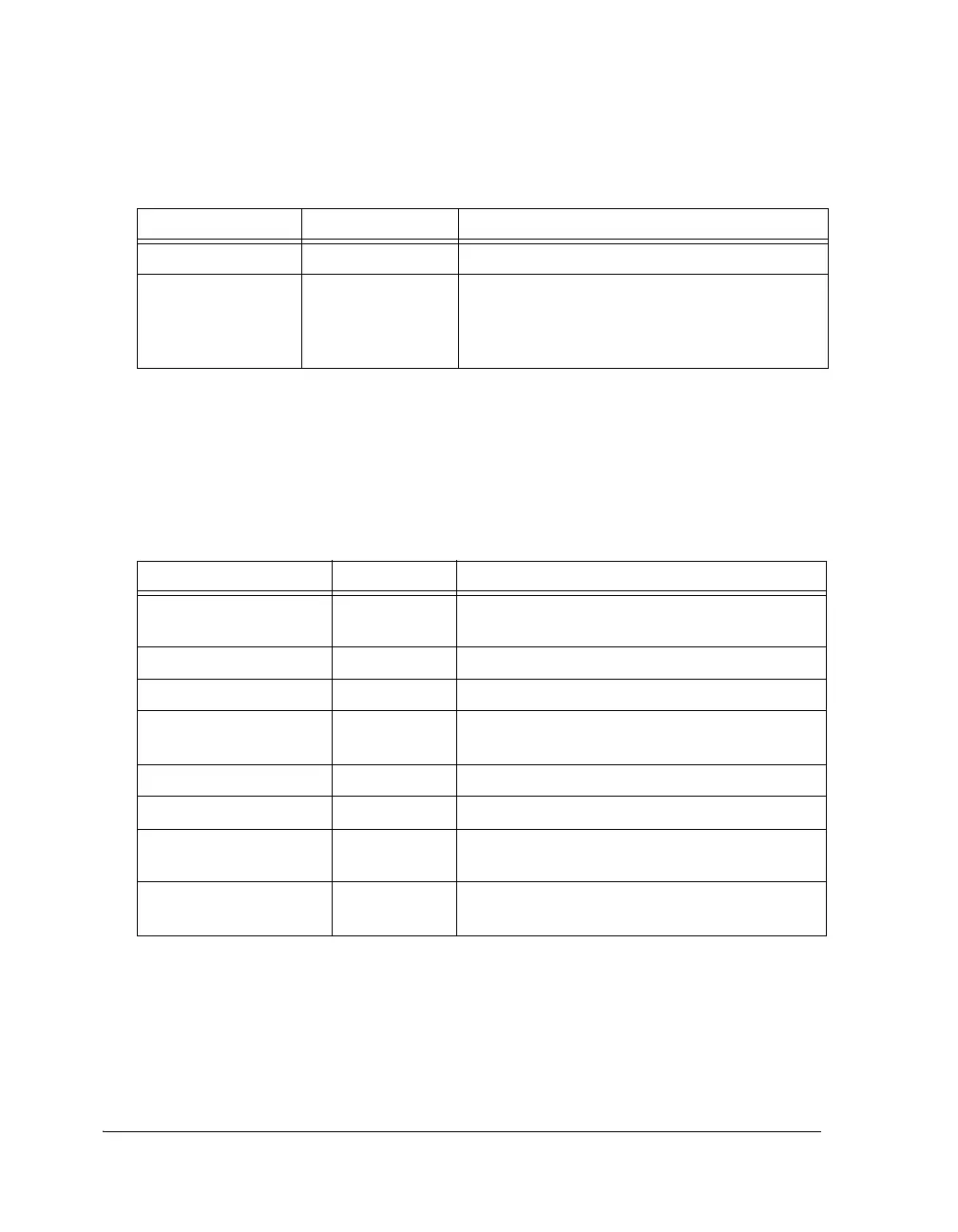
Table 13-3 provides descriptions of the pins used for the S/PDIF receiver.
SRU Programming
The SRU (signal routing unit) is used to connect the S/PDIF transmitter
biphase data out to the output pins or to the S/PDIF receiver. The serial
DIT_O Output Transmit Biphase Mark Encoded Data Stream.
DIT_BLKSTART_O Output Tr a n s m i t Bl o c k S t a r t . Indicates the last frame of the
current block. This is high for the entire duration of
the last frame. This can also be connected to the
DAI interrupts 31–22 using SRU_MISCx registers.
1 Timing for the S/PDIF format consists of time slots, unit intervals, subframes, and frames. For a
complete explanation of S/PDIF timing, see one of the digital audio interface standards listed in
the “Features” section of this chapter.
Table 13-3. S/PDIF Receiver Pin Descriptions
Internal Node I/O Description
SPDIF_EXTPLLCLK_I Input PLL clock input (512
× FS). Input clock from
external PLL.
DIR_I Input Biphase mark encoded data receiver input stream.
DIR_CLK_O Output Extracted receiver sample clock output.
DIR_TDMCLK_O Output Receiver TDM clock out. This clock is 256
×
DIR_FS_O.
DIR_FS_O Output Extracted receiver frame sync out.
DIR_DAT_O Output Extracted audio data output.
DIR_LRCLK_FB_O Output Receiver frame sync feed back output. Input for
external PLL.
DIR_LRCLK_REF_O Output Receiver frame sync reference clock output. Input
for external PLL.
Table 13-2. S/PDIF Transmitter Pin Descriptions (Cont’d)
Internal Node I/O Description

 Loading...

