ADSP-214xx SHARC Processor Hardware Reference 21-25
Two Wire Interface Controller
•Set the
RSTART bit (or earlier when TWIMCTL register is pro-
grammed first).
•Set the TWIMDIR bit to indicate the next transfer direction is
receive. This should be done before the addressing phase of
the next transfer begins.
• TWIMCOMP interrupt
This interrupt is generated because all data has been transferred
(DCNT = 0). If no errors were generated, a start condition is initi-
ated. At this time, program the following bits of TWI_MASTER_CTRL
register:
•Clear RSTART (if this is the last transfer).
• Re-program DCNT with the desired number of bytes to
receive.
• TWISERR interrupt
This interrupt is generated due to the arrival of a byte into the
receive FIFO. Simple data handling is all that is required.
Receive/Transmit Repeated Start Sequence
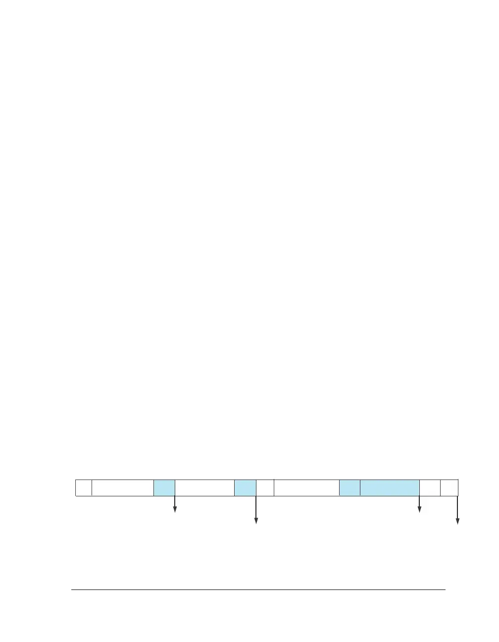
Figure 21-12 illustrates a repeated start data receive followed by a data
transmit sequence. The shading indicates the slave has the bus.
Figure 21-12. Receive/Transmit Data Repeated Start
ACKACKSS8-BIT DATA7-BIT ADDRESS ACK P8-BIT DATA ACK7-BIT ADDRESS
MCOMP INTERRUPT
XMTSERV INTERRUPT
RCVSERV INTERRUPT
MCOMP INTERRUPT

 Loading...

