Peripherals Routed Through the DAI
A-216 ADSP-214xx SHARC Processor Hardware Reference
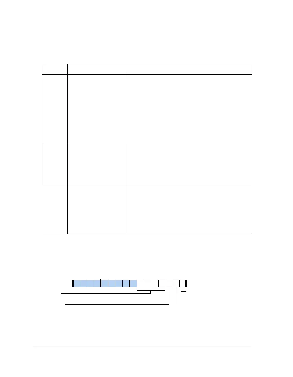
Initialization Status Register (RTC_INITSTAT)
Figure A-116 and Table A-116 describe the bits in the
RTC_INITSTAT
register.
Table A-115. RTC_INIT Register Bit Descriptions (RW)
Bit Name Description
3–0 CALIB
Time Calibration. Max
± 7 seconds. Calibration value is
added/subtracted from the time every day at midnight.
1001 -> –1 second
1010 -> –2 second
----------------------
1111 -> –7 second
0001 -> +1 second
0010 -> +2 second
-----------------------
0111 -> +7 second
4RTCPDN RTC Power Down. Active high.
Write 1 to power down RTC oscillator, 0 to power up
RTC oscillator. This bit must be compulsorily written
once during first RTC oscillator power-up.
0 = RTC oscillator runnng
1 = Powers down RTC oscillator
5 RTC_READEN Output Bus Enable. Enables the output buses between
RTC I/O voltage portion and RTC core voltage portion.
Setting this bit grounds these buses and prevents floating
node consumption when the RTC is not used. At reset,
the output buses are enabled (this bit is cleared).
0 = Buses are enabled (RTC in use)
1 = Buses are disabled (RTC not in use)
Figure A-116. RTC_INITSTAT Register
ALRM_PEND
Alarm Occurred
DAYALRM_PEND
Day Alarm Occurred
RTCPDN_STAT
Oscillator Power Down
09 837564 2114 12 11 101315
CALIB_STAT
Calibration Status

 Loading...

