ADSP-214xx SHARC Processor Hardware Reference A-213
Registers Reference
Stopwatch Count Register (RTC_SWTCH)
This register, shown in Figure A-112, contains the countdown value for
the stop watch. The stopwatch counts down seconds from the pro-
grammed value and generates an interrupt (if
SW_INTEN = 1) when the
count reaches 0. The counter stops counting at this point and does not
resume counting until a new nonzero value is written to this register.
Writing a value of 0 to the running stopwatch forces it to stop; no inter-
rupt is generated in this case. The register can be programmed to any
value between 0 and (2
16
– 1) seconds (that is, a range of 18 hours, 12
minutes and 15 seconds).
5DAY Day Event Flag.
0 = Day event has not occurred
1 = Day event has occurred (clock counter value
x:23:59:59)
6ALRM Alarm Flag.
0 = Daily alarm has not occurred
1 = Daily alarm has occurred
7DAYALRM Time of Day Flag.
0 = Alarm has not occurred
1 = Alarm has occurred
8 SW_EXP Stop Watch Counter Expiration Flag.
0 = Stop watch counter has not expired
1 = Stop watch counter expired
9RTC_CKFAIL Disables/Enables RTC interrupts in emulation mode.
0 = RTC 1 Hz clock is functional
1 = RTC 1 Hz clock failed
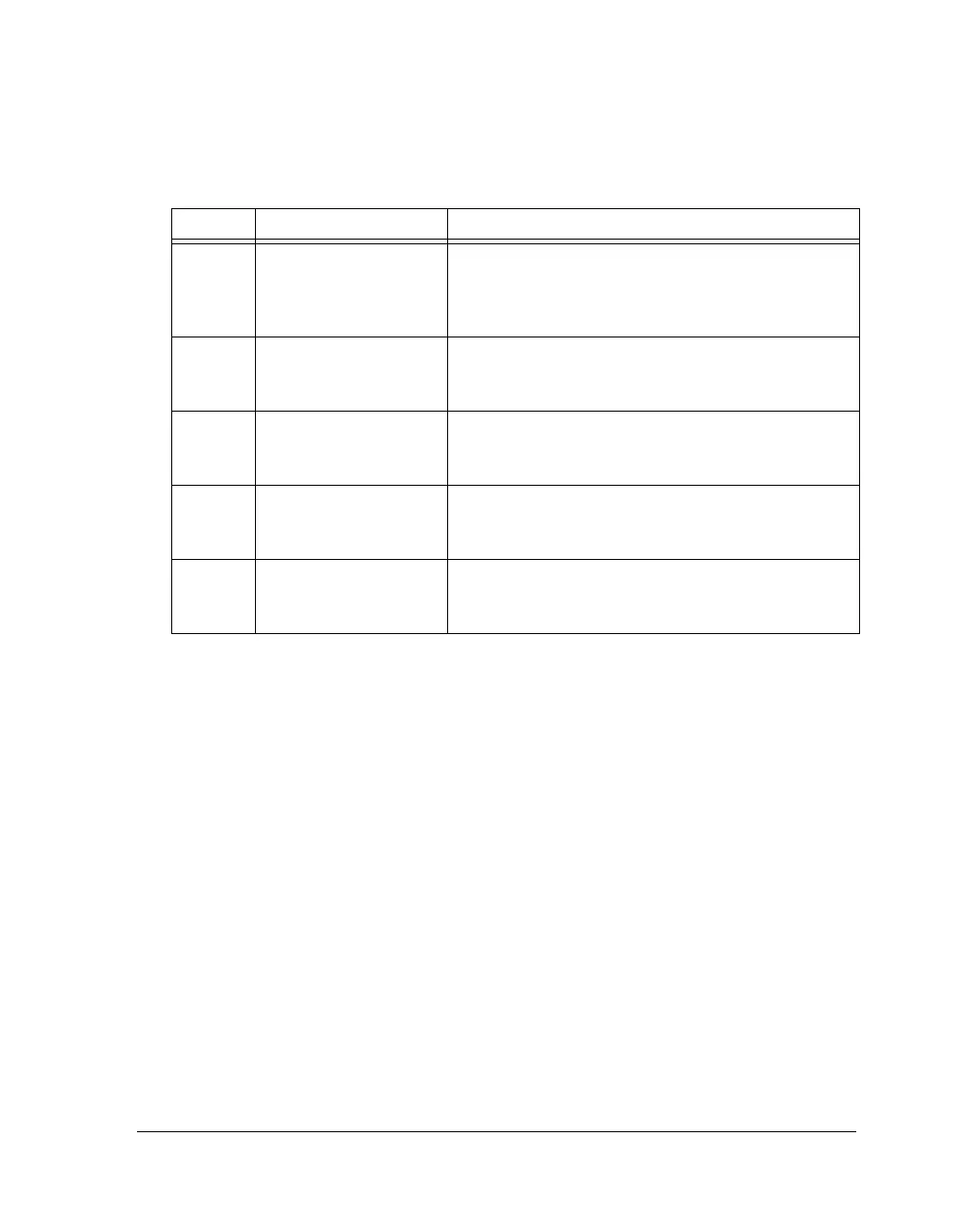
Table A-114. RTC_STAT Register Bit Descriptions (RO) (Cont’d)
Bit Name Description

 Loading...

