Operation Modes
7-22 ADSP-214xx SHARC Processor Hardware Reference
Single Update Mode
In single update mode, a single PWM interrupt is produced in each PWM
period. The rising edge of this signal marks the start of a new PWM cycle
and is used to latch new values from the PWM configuration registers
(
PWMTM and PWMDT) and the PWM duty cycle registers (PWMCHx) into the
two-phase timing unit. In addition, the PWMSEG register is also latched into
the output control unit on the rising edge of the PWM interrupt latch
pulse. In effect, this means that the characteristics and resultant duty
cycles of the PWM signals can be updated only once per PWM period at
the start of each cycle. The result is that PWM patterns that are symmetri-
cal about the mid-point of the switching period are produced.
Double Update Mode
In double update mode, there is an additional PWM interrupt latch pulse
produced at the mid-point of each PWM period. The rising edge of this
new PWM pulse is again used to latch new values of the PWM
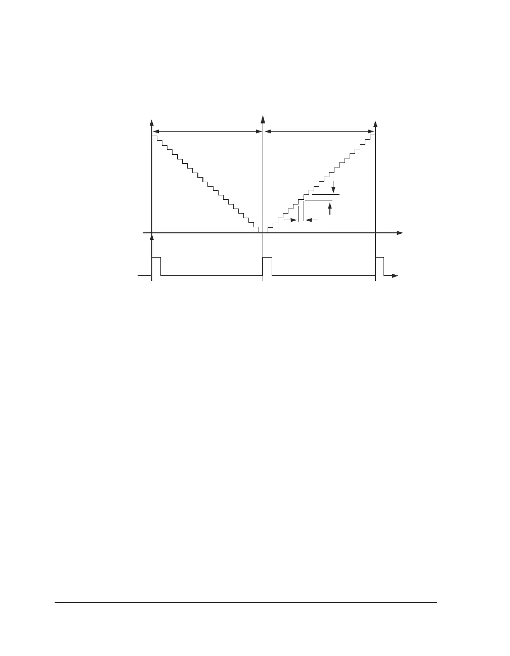
Figure 7-7. Operation of Internal PWM Timer (Edge Aligned)
PWM TIME DECREMENTS FROM
PWMPERIOD/2 TO
-
PWMPERIOD/2
PWMPERIOD/2
1
PCLK
PWM INTERRUPT
LATCH
PWM TIME DECREMENTS FROM
-
PWMPERIOD/2 TO PWMPERIOD/2
-
PWMPERIOD/2

 Loading...

