ADSP-214xx SHARC Processor Hardware Reference 23-23
System Design
Kernel Boot Time
This section illustrates the minimum required booting time for the kernels
(provided by the tools). There are five timing windows which describe
together the entire boot process shown in the list below and Table 23-13.
1.
RESET to RESETOUT (core is in reset)
2.
RESETOUT to chip select boot source (activate the boot DMA)
3. Load Kernel DMA (256 words)
4. Load application (user dependent)
5. Load IVT (256 words)
The complete time for booting can be estimated by adding all 5 timing
windows. Loading Kernel and Loading IVT both have the same size, how-
ever the default access time (wait states) for the IVT loading can be
changed in the kernel by the user.
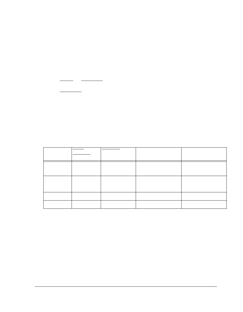
Table 23-13. Boot Times
Boot Mode RESE T to
RESETOUT
RESETOUT to Boot
Chip Select
Kernal DMA (256
Words )
Comment
SPI Master 4096 CLKIN 1 PCLK
(I/O × PCLK
÷ 100 +
4 × PCLK) × N
N=384, 768 or 1536 for
I/O = 32, 16 or 8
SPI Slave 4096 CLKIN Host drives signal
(I/O
× PCLK ÷ 100 +
2 ×
PCLK) × N
N=384, 768 or 1536 for
I/O = 32, 16 or 8
External Port 4096 CLKIN 5 PCLK 24 × SDCLK × 1536
Link Port0 4096 CLKIN Host drives signal LCLK0 × 1536

 Loading...

