ADSP-214xx SHARC Processor Hardware Reference 20-11
UART Port Controller
(
UARTTHR) initiates the transmit operation and reads from this address
return the UARTRBR register.
Note that data is transmitted and received by the least significant bit
(LSB) first (bit 0) followed by the most significant bits (MSBs).
Receive Buffer Registers (UARTRBR)
The receive operation uses the same data format as the transmit configura-
tion, except that the number of stop bits is always assumed to be 1. After
detection of the start bit, the received word is shifted into the receive shift
register (UARTRSR) at a baud rate of PCLK/(16 x Divisor). After the appro-
priate number of bits (including stop bit) is received, the data and any
status are updated and the
UARTRSR register is transferred to the UART
receive buffer register (UARTRBR), shown in Figure 20-4. After the transfer
of the received word to the
UARTRBR buffer and the appropriate synchroni-
zation delay, the data ready status flag (
UARTDR) is updated.
A sampling clock equal to 16 times the baud rate samples the data as close
to the midpoint of the bit as possible. Because the internal sample clock
may not exactly match the asynchronous receive data rate, the sampling
point drifts from the center of each bit. The sampling point is synchro-
nized again with each start bit, so the error accumulates only over the
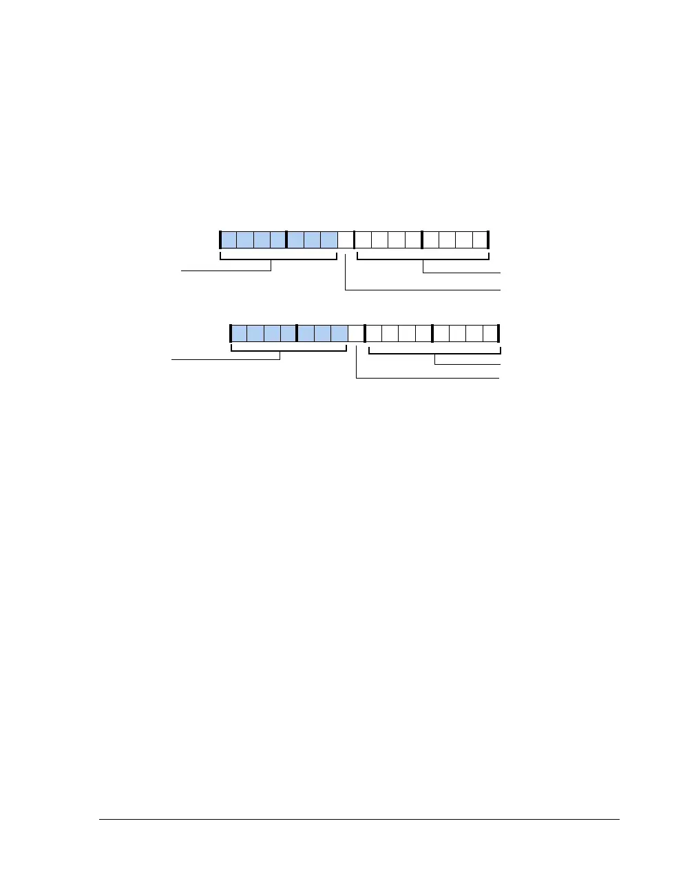
Figure 20-3. UART Transmit Holding Register (Packing Enabled)
TX9D0
TX9D1
Zero-Filled
Zero-Filled
09 837564 2114 12 11 101315
31 302928 27 26 25 24 23 22 21 20 19 18 17 16
Higher Byte (23–16)
Lower Byte (7–0)

 Loading...

