Pin Descriptions
7-4 ADSP-214xx SHARC Processor Hardware Reference
Pin Descriptions
The PWM module has four groups of four PWM outputs each, for a total
of 16 PWM outputs. These outputs are described in Table 7-2.
Multiplexing Scheme
By default the PWM output pins are disabled. To enable the PWM units
refer to Table 23-15 on page 23-30. Table 7-3 and Table 7-3 show the
connection to the PWM outputs on the external port pins. For more
information, see “Pin Multiplexing” on page 23-28.
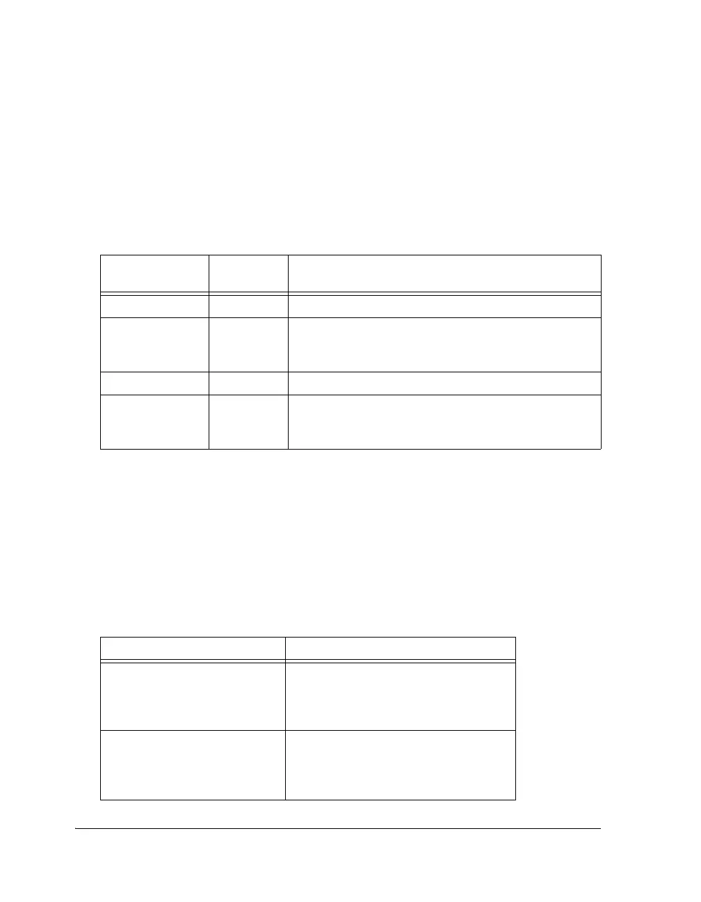
Table 7-2. PWM Pin Descriptions
Multiplexed Pin
Name
Direction Description
PWM_AH3–0 O PWM output of pair A produce high side drive signals.
PWM_AL3–0 O PWM output of pair A produce low side
drive signals. Note in paired mode, this pin is the comple-
ment of AH3-0.
PWM_BH3–0 O PWM output of pair B produce high side drive signals.
PWM_BL3–0 O PWM output of pair A produce low side
drive signals. Note in paired mode, this pin is the comple-
ment of BH3-0.
Table 7-3. PWM Connections
PWM Unit Pin Multiplexing
PWM0 AMI_ADDR8 = AL0
AMI_ADDR9 = AH0
AMI_ADDR10 = BL0
AMI_ADDR11 = BH0
PWM1 AMI_ADDR12 = AL1
AMI_ADDR13 = AH1
AMI_ADDR14 = BL1
AMI_ADDR15 = BH1

 Loading...

