Operating Modes
12-14 ADSP-214xx SHARC Processor Hardware Reference
cycles per subframe in matched-phase mode (24-bits data and 8-bits phase
match).
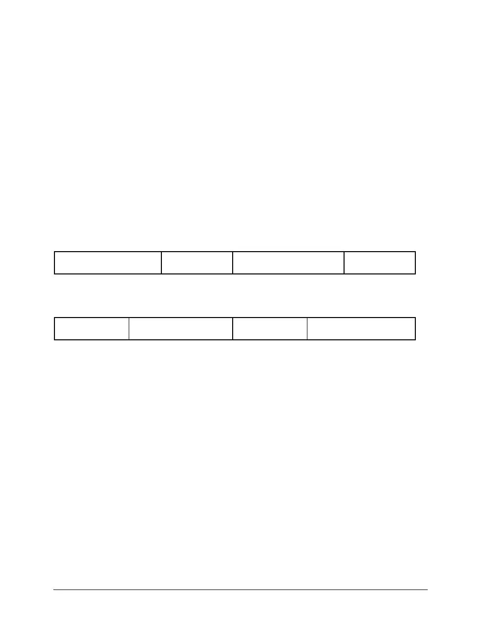
Data Format Matched-Phase Mode
The SRC supports the matched-phase mode for all serial output data for-
mats; left-justified, I
2
S, right-justified, and TDM mode. Note that in the
left-justified, I
2
S, and TDM modes, the lower 8 bits of each channel sub-
frame are used to transmit the matched-phase data. In right-justified
mode, the upper eight bits are used to transmit the matched-phase data.
This is shown in Figure 12-6.
Group Delay
When multiple SRCs are used with the same serial input port clock and
the same serial output port clock, the hysteresis causes different group
delays (phase mismatches) between multiple SRCs. The filter group delay
of the SRC is given by the equations:
Figure 12-6. Matched-Phase Data Transmission
AUDIO DATA RIGHT
CHANNEL, 16 BITS - 24 BITS
MATCHED-PHASE
DATA, 8 BITS
MATCHED-PHASE
DATA, 8 BITS
AUDIO DATA LEFT
CHANNEL, 16 BITS - 24 BITS
Left-Justified, I
2
S, and TDM Mode
Right-Justified Mode
AUDIO DATA LEFT CHANNEL,
MATCHED-PHASE
DATA, 8 BITS
AUDIO DATA RIGHT
24 BITS
CHANNEL, 24 BITS
MATCHED-PHASE
DATA, 8 BITS
GDS
16
SRCx_FS_IP
-------------------------------
32
SRCx_FS_IP
------------------------------- onds for SRCx_FS_OP SRCx_FS_IP≥()sec+=

 Loading...

