ADSP-214xx SHARC Processor Hardware Reference A-69
Registers Reference
Global Status Register (PWMGSTAT)
This register provides the status of each PWM group (Table A-36). The
status bits are set depending on the
IRQEN bit. The ISR needs to write one
to clear the status bits.
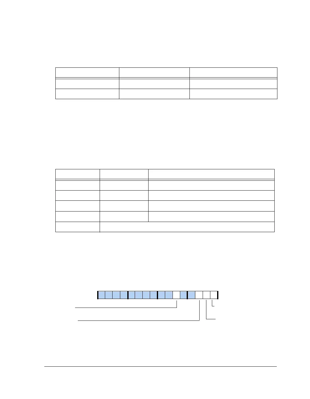
Control Register (PWMCTLx)
These registers, described in Table A-37, are used to set the operating
modes of each PWM block. They also allow programs to disable interrupts
from individual groups.
8, 10, 12, 14 PWM_SYNCENx PWM Group x Enable
9, 11, 13, 15 PWM_SYNCDISx PWM Group xDisable
Table A-36. PWMGSTAT Register Bit Descriptions (W1C)
Bit Name Function
0 PWM_STAT0 PWM Group 0 Period Completion Status
1 PWM_STAT1 PWM Group 1 Period Completion Status
2 PWM_STAT2 PWM Group 2 Period Completion Status
3 PWM_STAT3 PWM Group 3 Period Completion Status
15–4 Reserved
Figure A-32. PWMCTLx Register
Table A-35. PWMGCTL Register Bit Descriptions (RW) (Cont’d)
Bit Name Function
PWM_ALIGN
Pair Mode
Align Mode
PWM_PAIR
PWM_IRQEN
Interrupt Enable
PWM_UPDATE
Update Mode
09 837564 2114 12 11 101315

 Loading...

