ADSP-214xx SHARC Processor Hardware Reference A-271
Registers Reference
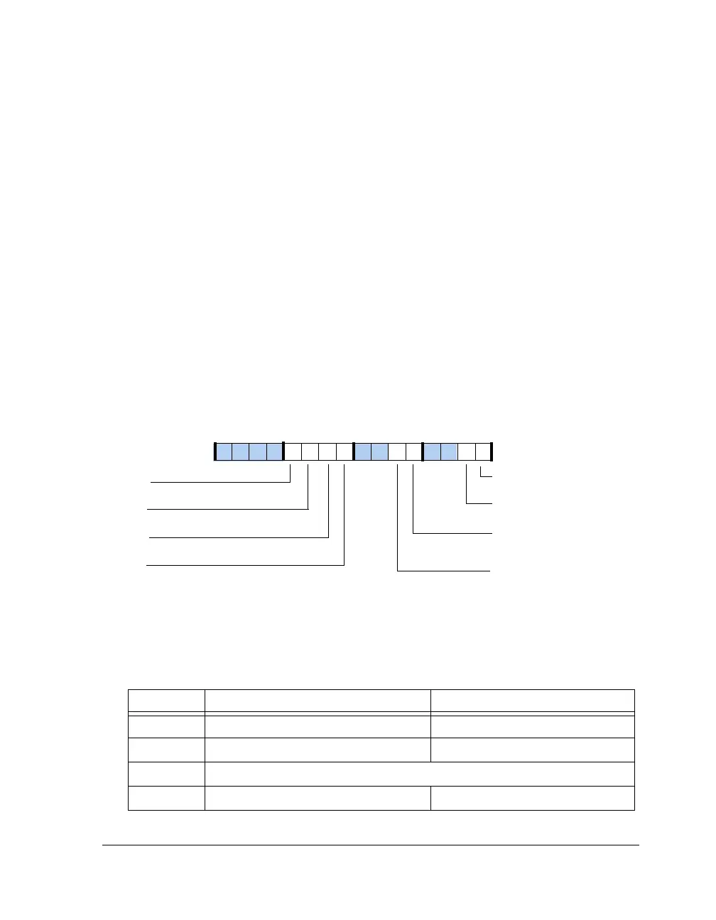
Timer Status Registers (TMxSTAT)
The global status registers
TMxSTAT are shown in Figure A-156. Status bits
are sticky and require a write-one to clear operation. During a status
register read access, all reserved or unused bits return a zero. Each timer
generates a unique processor interrupt request signal, TIMxIRQ.
A common status register latches these interrupts. Interrupt bits are sticky
and must be cleared to assure that the interrupt is not reissued.
Each timer is provided with its own sticky status register TIMxEN bit. To
enable or disable an individual timer, the TIMxEN bit is set or cleared. For
example, writing a one to bit 8 sets the TIM0EN bit; writing a one to bit 9
clears it. Writing a one to both bit 8 and bit 9 clears TIM0EN. Reading the
status register returns the TIM0EN state on both bit 8 and bit 9. The
remaining TIMxEN bits operate similarly.
Figure A-156. TMxSTAT Register
Table A-147. TMxSTAT Register Bit Descriptions (RW)
Bit Name Description
0 (W1C) TIM0IRQ Timer 0 Interrupt Latch Also an output
1 (W1C) TIM1IRQ Timer 1 Interrupt Latch Also an output
3–2 Reserved
4 (RO) TIM0OVF Timer 0 Overflow/Error Also an output
TIM1DIS
TIM1EN
Timer 1 Disable
Timer 1 Enable
TIM0DIS
TIM0EN
Timer 0 Disable
Timer 0 Enable
TIM0IRQ
Timer 0 Interrupt
TIM1IRQ
Timer 1 Interrupt
TIM0OVF
Timer 0 Counter
Overflow Error
TIM1OVF
Timer 1 Counter
Overflow Error
09 837564 2114 12 11 101315

 Loading...

