Processor Booting
23-18 ADSP-214xx SHARC Processor Hardware Reference
Figure 23-5 shows how a pair of instructions are packed for SPI booting
using a 32-, 16-, and an 8-bit device. These two instructions are received
as three 32-bit words.
The following sections examine how data is packed into internal memory
during SPI booting for SPI devices with widths of 32, 16, or 8 bits.
32-Bit SPI Packing
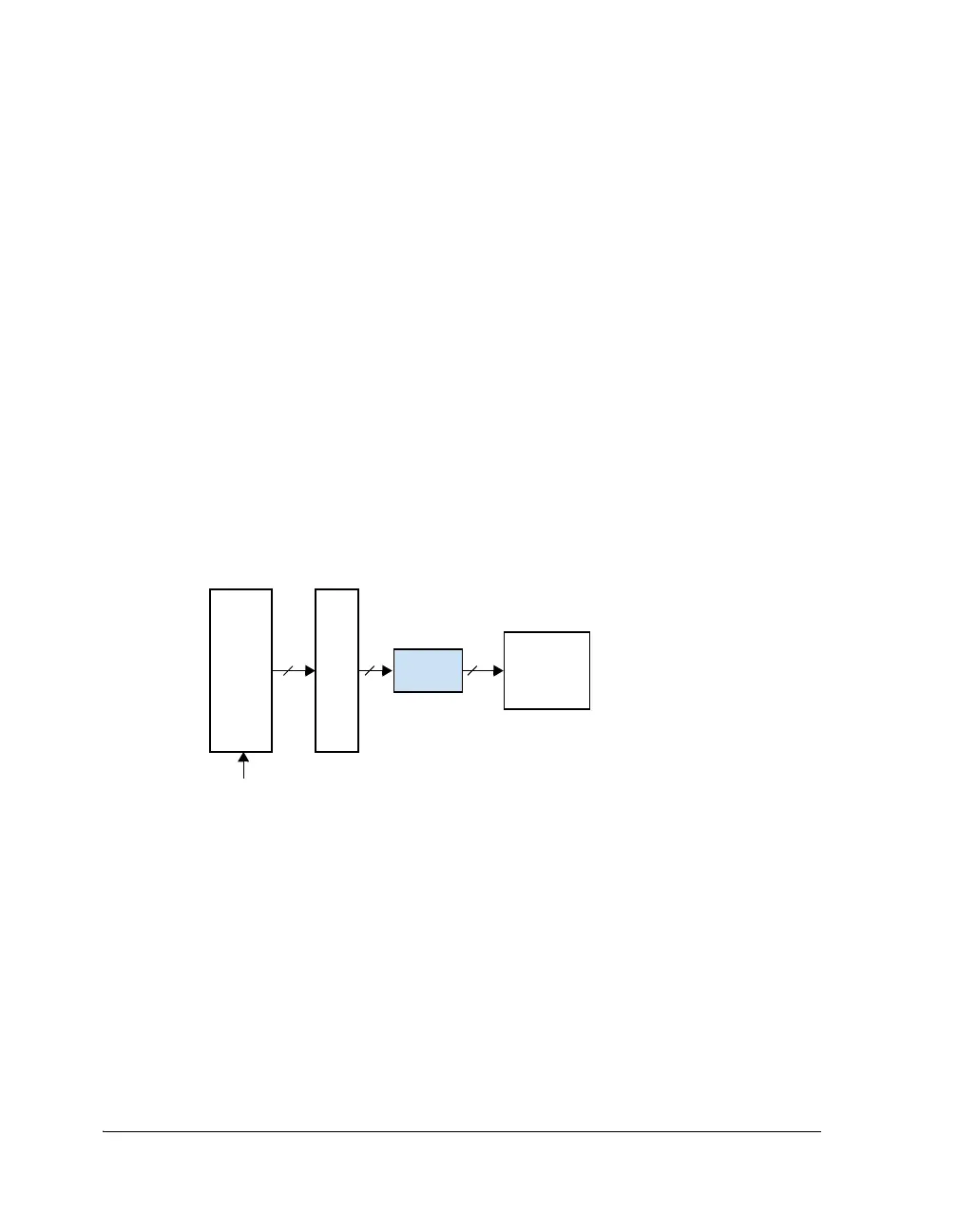
Figure 23-6 shows how a 32-bit SPI host packs 48-bit instructions exe-
cuted at PM addresses PMaddr0 and PMaddr1. The 32-bit word is shifted
to internal program memory during the 256-word kernel load.
The following example shows a 48-bit instruction executed:
[PMaddr0] 0x112233445566
[PMaddr1] 0x7788AABBCCDD
The 32-bit SPI host packs or prearranges the data as:
The initial boot of the 256-word loader kernel requires a 32-bit host to
transmit 384 x 32-bit words. The SPI DMA count value of 0x180 is equal
to 384 words.
Figure 23-6. 32-Bit SPI Master/Slave Packing
SPI word 1= 0x33445566
SPI word 2 = 0xCCDD1122
SPI word 3 = 0x7788AABB
SPI_MOSI_I/SPI_MISO_I
RXSR
Word N
RXSPI
Internal
Memory
32 32
32
DMA
32-bit

 Loading...

