ADSP-214xx SHARC Processor Hardware Reference A-7
Registers Reference
Power Management Control Registers (PMCTL)
The following sections describe the registers associated with the processors
power management functions.
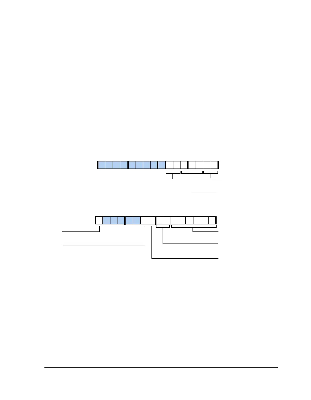
The power management control register, shown in Figure A-2, is a 32-bit
memory-mapped register. This register contains bits to control phase lock
loop (PLL) multiplier and divider (both input and output) values, PLL
bypass mode, and clock enabling control for peripherals (see Table A-3 on
page A-8). This register also contains status bits, which keep track of the
status of the
CLK_CFG pins (read-only). The reset value of PMCTL is depen-
dent on the CLK_CFG pins (bits 5–0 and 17–16).
Figure A-2. PMCTL Register
PLLBP
DIVEN
CRAT (17–16)
PLL Clock Ratio
PLLM (5–0)
PLL Multiplier
PLL Divider Enable
PLLD (7–6)
PLL Divider
INDIV
Input Divider
PLL Bypass
DDR2CKR
Core Clock to DDR2 Clock
LCLKR (22–21)
Link Port Clock Ratio
31 302928 27 26 25 24 23 22 21 20 19 18 17 16
09 837564 2114 12 11 101315

 Loading...

