ADSP-214xx SHARC Processor Hardware Reference 4-5
Link Ports—ADSP-2146x
Architecture
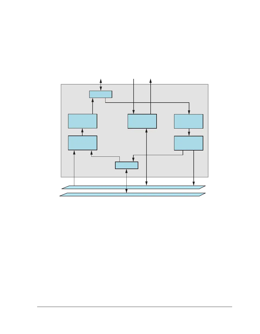
Figure 4-2 shows the architecture of the link ports.
Protocol
A link-port-transmitted word consists of 4 bytes (for a 32-bit word). The
transmitter asserts the clock (
LCLKx) high with each new byte of data. The
falling edge of
LCLKx is used by the receiver to latch the byte. The receiver
asserts LACKx when it is ready to accept another word in the receive buffer,
RXLBx. The transmitter samples LACKx driven by the receiver at the begin-
ning of each word transmission (that is, after every 4 bytes with a positive
level latch). If
LACKx is deasserted at that time, the transmitter does not
transmit the new word. The transmitter leaves
LCLKx high and continues
Figure 4-2. Link Port Block Diagram
LDATx7
-
0
TRANSMIT
SHIFT
BUFFER
TRANSMIT
BUFFER
(2 DEEP)
RECEIVE
SHIFT
REGISTER
RECEIVE
BUFFER
(2 DEEP)
CONTROL
STATUS
LTRAN
DMA
LACKx LCLKx
IOD BUS
PM/DM DATA BUS

 Loading...

