Functional Description
4-6 ADSP-214xx SHARC Processor Hardware Reference
to drive the first byte if
LACKx is deasserted. When LACKx is eventually
asserted again, the transmitter drives LCLKx low and begins transmission of
the next word. If the transmit buffer is empty, LCLKx remains low until the
buffer is refilled, regardless of the state of LACKx.
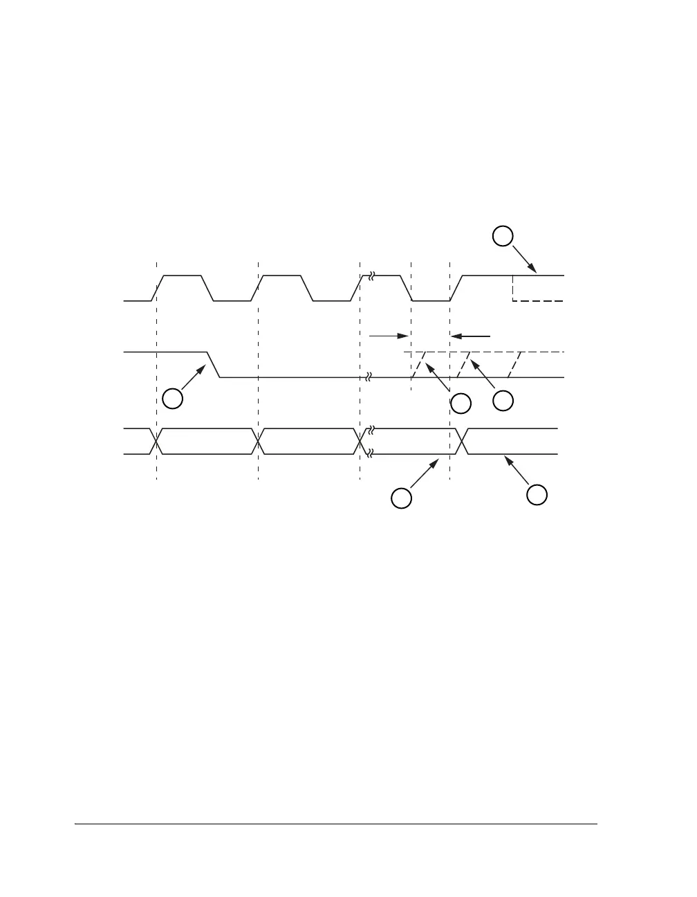
The following list describes the stages shown in Figure 4-3.
1.
LCLK stays high at byte 0 if LACK is sampled low on the previous
LCLK rising edge. LCLK high indicates a stall.
2. LxACK may deassert after byte 0.
3.
LACK reasserts as soon as the link buffer is not full.
4. Transmitter samples LACK to determine whether to transmit the
next word.
Figure 4-3. Link Port Handshake Timing
LXCLK
LXACK
LXDAT7-0
BYTE 1 BYTE 2 BYTE 0 (LSBs)
MINIMUM LACK SET-UP TIME
BYTE 3 (32-BIT)
1
2
3
4
5
6

 Loading...

