ADSP-214xx SHARC Processor Hardware Reference 16-15
Peripheral Timers
External Event Watchdog Mode (EXT_CLK)
Figure 16-7 shows a flow diagram for EXT_CLK mode. To enable
EXT_CLK mode, set the TIMODE1–0 bits in the TMxCTL register to 11 in the
TMxCTL register. This samples the TIMERx_I signal as an input. Therefore,
in EXT_CLK mode, the TMxCNT register should not be read when the
counter is running.
The operation of the EXT_CLK mode is as follows:
1. Program the TMxPRD period register with the value of the maximum
timer external count.
2. Set the
TIMxEN bits. This loads the period value in the count regis-
ter and starts the countdown.
3. When the period expires, an interrupt, (TIMxIRQ) occurs.
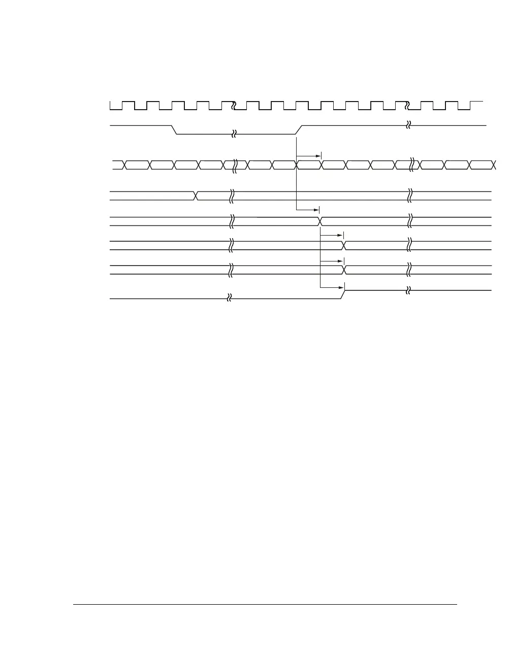
Figure 16-6. WDTH_CAP Timing (Period Count = 1)
PCLK
TIMERx_I
W_BUF
P_BUF
PERIOD
WIDTH
IRQ
P
P/2
W/2
P
COUNTER
W + 1W - 1 W P - 2 P - 1 1 02
cycle
cycle
cycle
cycle
cycle
W
synchronized

 Loading...

