ADSP-214xx SHARC Processor Hardware Reference A-3
Registers Reference
• The bit descriptions in the figures are intentionally brief, contain-
ing only the bit mnemonic, location, and function. More detailed
information can be found in the tables that follow the register
drawings and in the chapters that describe the particular module.
• Shaded bits are reserved.
• The VisualDSP++ tools suite contains the complete listing of regis-
ters in a header file,
def214xx.h.
• “Register Listing” on page A-273 provides a complete list of user
accessible registers, their addresses, and their state at reset.
Bit Types and Settings
There are several bit types used in SHARC registers. These are described
in Table A-1. In general, control register bits are read-write (RW) and sta-
tus register bits are read-only (RO). In exceptional cases, bit types are
shown in the “Bit” column in parenthesis where for example a RO bit is
used in a control register or for write-one-to-clear (W1C) bits.
Also note that the setting after reset (default setting) of most bits is 0
(cleared). In cases where this is not true, this is shown in the “Description”
column in parenthesis.
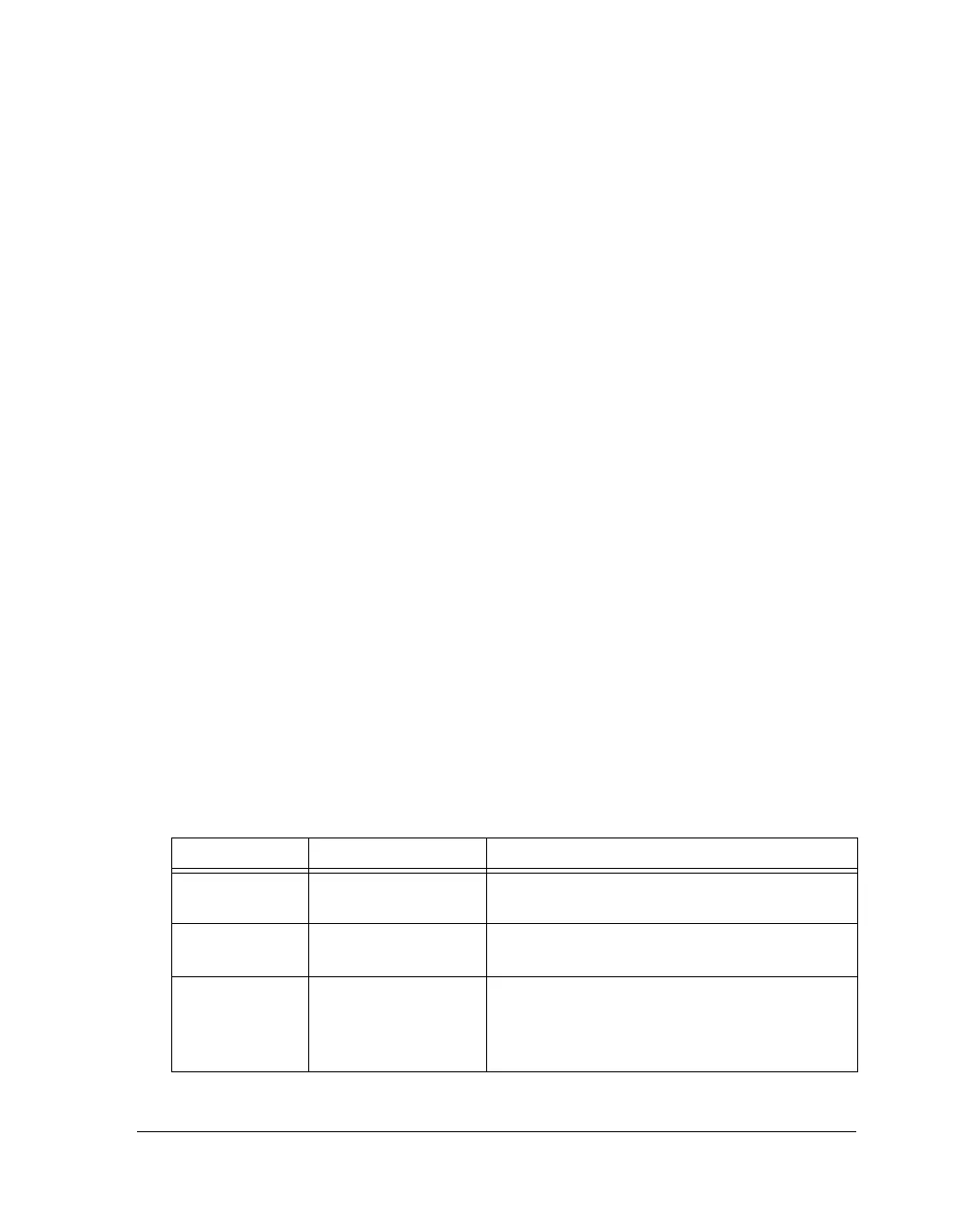
Table A-1. Bit Type Usage
Bit Type Description Usage
RW Read-Write RW bits are used primarily in control registers and
DMA parameter and count registers.
RO Read-Only RO bits are used primarily in status registers and
Shadow registers/buffers for debug aid.
ROC Read-Only-to-Clear ROC bits are used to clear receive buffer status bits.
These bits are also used on the DAI/DPI interrupt
controllers. These bits are sticky and their status is
only cleared after a read.

 Loading...
