Data Transfer
11-18 ADSP-214xx SHARC Processor Hardware Reference
The polarity of left-right encoding is independent of the serial mode frame
sync polarity selected in
IDP_SMODE for that channel (Table 11-3 on
page 11-3). Note that I
2
S mode uses a LOW frame sync (left-right) signal to
dictate the first (left) channel, and left-justified mode uses a HIGH frame
sync (left-right) signal to dictate the first (left) channel of each frame. In
either mode, the left channel has bit 3 set (= 1) and the right channel has
bit 3 cleared (= 0).
PDAP Data Buffer Format
If the PDAP module is enabled the IDP data buffer format will change
according to the PDAP packing bits (
IDP_PDAP_CTL register) as shown in
Figure 11-9.
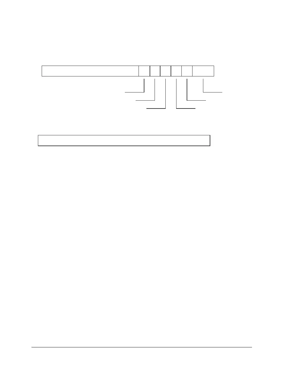
Figure 11-8. IDP Data Buffer Format SIP – I2S/Left-Justified (32 Bits)
VALIDITY BIT
USER DATA
BLOCK STATUS
BIT
24-BIT AUDIO DATA
L/R BIT
3BITS
IDP CHANNEL
CHANNEL STATUS
BIT
I
2
S AND LEFT-JUSTIFIED FORMAT
I
2
S AND LEFT-JUSTIFIED FORMAT, 32-BIT DATA WIDTH
32 BIT DATA

 Loading...

