ADSP-214xx SHARC Processor Hardware Reference 20-7
UART Port Controller
Serial Communication
The UART follows an asynchronous serial communication protocol with
these options:
• 5 – 8 data bits
• 1 or 2 stop bits
• None, even, or odd parity
• Baud rate = PCLK/(16 × divisor), divisor value can be from 1 to
65,536
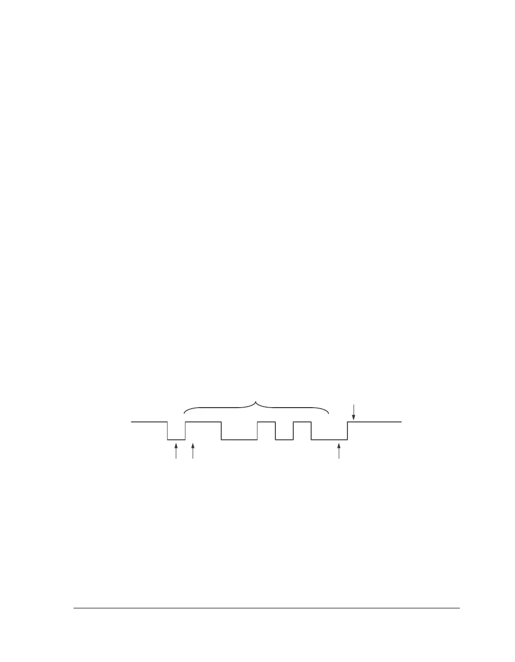
All data words require a start bit and at least one stop bit. With the
optional parity bit, this creates a 7 to 12-bit range for each word. The
format of received and transmitted character frames is controlled by the
line control register (UARTLCR). Data is always transmitted and received
least significant bit (LSB) first.
Figure 20-2 shows a typical physical bit stream measured on the transmit
pin.
Transmit and receive channels are both buffered. The
UARTTHR register
buffers the transmit shift register (
UARTTSR) and the UARTRBR register buf-
fers the receive shift register (
UARTRSR). The shift registers are not directly
accessible by software.
Figure 20-2. Bit Stream on the Transmit Pin
DATA BITS
STOP BIT(S)
START BIT LSB
PARITY BIT (OPTIONAL, ODD OR EVEN)
D0 D1 D2 D3 D4 D5 D6 D7

 Loading...

