Peripheral Registers
A-66 ADSP-214xx SHARC Processor Hardware Reference
Memory-to-Memory Registers
The following DMA related registers are used when performing inter-
nal-to-internal DMA through the MTM port.
DMA Control (MTMCTL Register)
The
MTMCTL register (Figure A-30) allows programs to transfer blocks of
64-bit data from one internal memory location to another.
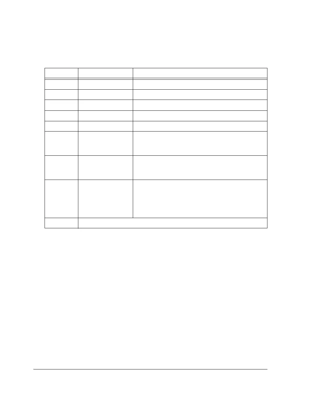
Table A-34. LSTATx Register Bit Descriptions (RO)
Bit Name Description
0 (ROC) LTRQ Link Port Transmit Request Status.
1 (ROC) LRRQ Link Port Receive Request Status.
2 (ROC) DMACH_IRPT DMA Channel Count Interrupt.
3 (ROC) LPIT Link Port Invalid Transmit Interrupt.
4 (ROC) EXTTXFR_DONE External Transfer Done Interrupt.
6–5 FFST Link Buffer Status.
00 = empty, 01 = reserved, 10 = one word, 11 = full
(Cleared when the Link Port is disabled)
7LERR Link Buffer Receive Pack Error Status.
0 = Packing complete
1 = Packing incomplete
8LPBS Link Port Bus Status (Transmitter). To safely disable
linkport transmit operation first poll the FFST bit and
second the LPBS bit.
0 = Bus is idle
1 = Bus busy
31–9 Reserved

 Loading...

