ADSP-214xx SHARC Processor Hardware Reference 7-21
Pulse Width Modulation
PWM Timer Edge Aligned Update
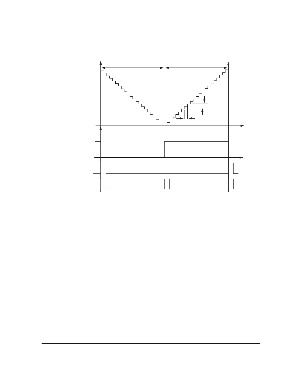
The internal operation of the PWM generation unit is controlled by the
PWM timer which is clocked at the peripheral clock rate, PCLK. The oper-
ation of the PWM timer over one full PWM period is illustrated in
Figure 7-7. It can be seen that during the first half cycle, the PWM timer
decrements from PWMPERIOD/2 to 0 using a two’s-complement count.
At this point, the count direction changes and the timer continues to
increment from 0 to the PWMPERIOD/2 value.
Also shown in Figure 7-7 are the PWM interrupt pulses for operation in
edge aligned mode. An PWM interrupt is latched at the beginning of
every PWM cycle. Note that the
PWMPHASE bit (PWMSTAT register) has no
meaning in this mode and is always set.
Figure 7-6. Operation of Internal PWM Timer (Center Aligned)
PWM TIME DECREMENTS FROM
PWMPERIOD/2 TO
-
PWMPERIOD/2
PWMPHASE BIT
1
PCLK
PWM INTERRUPT LATCH
(SINGLE UPDATE MODE)
PWM INTERRUPT LATCH
(DOUBLE UPDATE MODE)
PWM TIME DECREMENTS FROM
-
PWMPERIOD/2 TO PWMPERIOD/2
PWMPERIOD/2
-
PWMPERIOD/2

 Loading...

