ADSP-214xx SHARC Processor Hardware Reference 23-15
System Design
Slave Boot Mode
In slave boot mode, the host processor initiates the booting operation by
activating the
SPICLK signal and asserting the SPIDS signal to the active
low state. The 256-word kernel is loaded 32 bits at a time, through the
SPI receive shift register (RXSR). To receive 256 instructions (48-bit
words) properly, the SPI DMA initially loads a DMA count of 0x180
(384) 32-bit words, which is equivalent to 0x100 (256) 48-bit words.
Note that for SPI slave boot
SPIDS should only be asserted after RESETOUT
has deasserted.
When in SPI slave booting mode, the SPI_DS_I input signal is con-
trolled by the SPI host to initiate the boot transfers as shown in
Table 23-9.
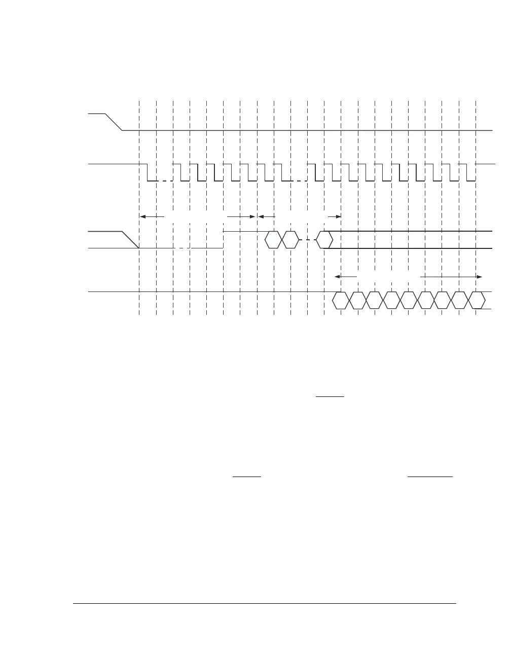
Figure 23-4. SPI Master Mode Booting Using Various Serial Devices
SPI_FLG0_O
SPI_CLK_O
0 1 4 5 6 7 8 9 22232425262728293031
SPI_MOSI_O
8-BIT INSTRUCTION
16-BIT ADDRESS
VALID EPROM BITS
WORD
SPI_MISO_i
 Loading...


