ADSP-214xx SHARC Processor Hardware Reference 12-3
Asynchronous Sample Rate Converter
• Linear phase FIR filter
• Controllable soft mute
Pin Descriptions
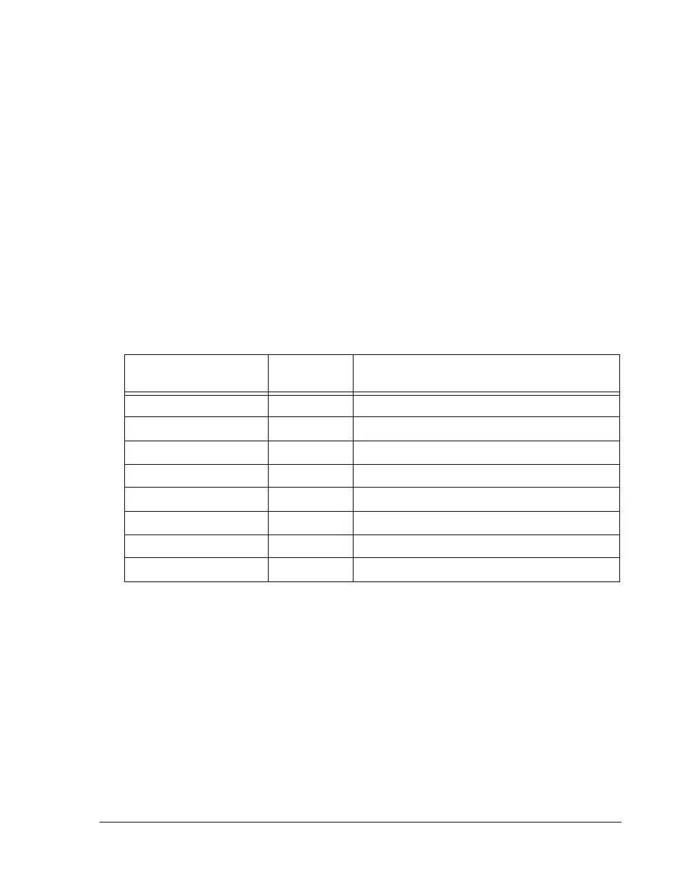
The SRC has two interfaces: an input port and an output port. Table 12-2
describes the six inputs and two outputs for the IP (input port) and OP
(output port).
SRU Programming
The SRU (signal routing unit) needs to be programmed in order to con-
nect the SRCs to the output pins or any other peripherals. For normal
operation, the data, clock, and frame sync signals need to be routed as
shown in Table 12-3.
Table 12-2. SRC Pin Descriptions
ADSP-214xx Internal
Node
I/O Description
SRC3–0_CLK_IP_I Input SRC input port clock input
SRC3–0_FS_IP_I Input SRC input port frame sync input
SRC3–0_DAT_IP_I Input SRC input port data input
SRC3–0_CLK_OP_I Input SRC output port clock input
SRC3–0_FS_OP_I Input SRC output port frame sync input
SRC3–0_TDM_OP_I Input SRC output port TDM daisy chain data input
SRC3–0_DAT_OP_O Output SRC output port data output
SRC3–0_TDM_IP_O Output SRC output port TDM daisy chain data output

 Loading...

