ADSP-214xx SHARC Processor Hardware Reference A-267
Registers Reference
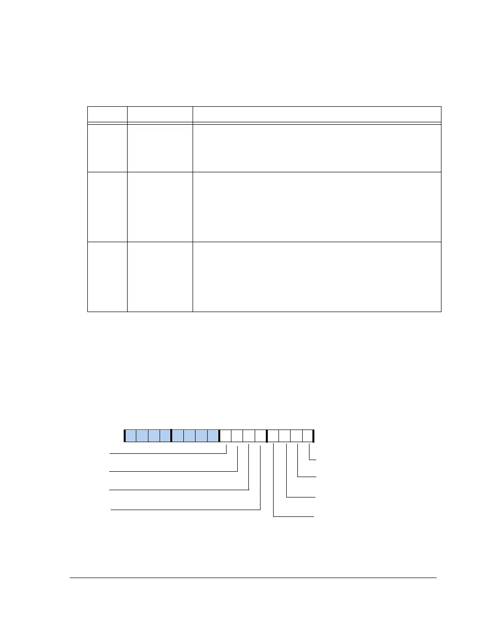
Interrupt Enable Register (TWIIMASK)
The TWI interrupt mask register (
TWIIMASK, shown in Figure A-154 and
described in Table A-145) enables interrupt sources to assert the interrupt
output. Each enable bit corresponds with one interrupt latch bit in the
TWI interrupt latch register (TWIIRPTL). Reading and writing the
TWIIMASK register does not affect the contents of the TWIIRPTL register.
5 TWIMERR Master Transfer Error.
0 = No errors detected
1 = A master error occurred. The conditions surrounding the error
are indicated by the master status register (TWIMSTAT).
6 TWITXINT Transmit FIFO Service.
0 = No errors detected
1 = The transmit FIFO buffer has one or two 8-bit locations avail-
able to be written. If TWITXINT2 is 0, this bit is set each time
TWITXS is updated to either 01 or 00. If TWITXINT2 is 1, this bit
is set each time TWITXS is updated to 00.
7 TWIRXINT Receive FIFO Service.
0 = No errors detected
1 = The receive FIFO buffer has one or two 8-bit locations contain-
ing data to be read. If TWIRXINT2 is 0, this bit is set each time
TWIRXS is updated to either 01 or 11. If RTWIRXINT2 is 1, this
bit is set each time TWIRXS is updated to 11.
Figure A-154. TWIIMASK Register
Table A-144. TWIIRPTL Register Bit Descriptions (W1X) (Cont’d)
Bit Name Description
TWISINIT
TWISCOMP
TWISERR
TWISOVF
TWIRXINT
TWITXINT
TWIMERR
TWIMCOM
Slave Transfer Initiate Interrupt Enable
Slave Transfer Complete Interrupt Enable
Slave Transfer Error Interrupt Enable
Slave Overflow Interrupt Enable
Receive FIFO Service Interrupt Enable
Transmit FIFO Service Interrupt Enable
Master Transfer Complete Interrupt Enable
Master Transfer Complete Interrupt Enable
09 837564 2114 12 11 101315

 Loading...

