ADSP-214xx SHARC Processor Hardware Reference A-141
Registers Reference
DAI Pin Buffer Enable Registers
(SRU_PBENx, Group F)
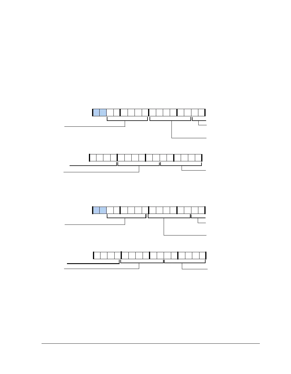
The pin enable control registers (see Figure A-77 through Figure A-80,
Table A-80) activate the drive buffer for each of the 20 DAI pins. When
the pins are not enabled (driven), they can be used as inputs.
Figure A-77. SRU_PBEN0 (RW)
Figure A-78. SRU_PBEN1 (RW)
DAI Port 5
Pin Buffer Enab le Input
PBEN05_I
DAI Port 3
Pin Buffer Enable Input
PBEN03_I
DAI Port 1
Pin Buffer Enable Input
PBEN01_I
DAI Port 4
Pin Buffer Enable Input
PBEN04_I
DAI Port 2
Pin Buffer Enable Input
PBEN02_I
PBEN03_I (23–18) (con’t)
31 302928 27 26 25 24 23 22 21 20 19 18 17 16
09 837564 2114 12 11 101315
DAI Port 10
Pin Buffer Enab le Input
PBEN10_I
DAI Port 8
Pin Buffer Enable Input
PBEN08_I
DAI Port 6
Pin Buffer Enab le Input
PBEN06_I
DAI Port 9
Pin Buffer Enable Input
PBEN09_I
DAI Port 7
Pin Buffer Enab le Input
PBEN07_I
PBEN08_I (23–18) (con’t)
31 302928 27 26 25 24 23 22 21 20 19 18 17 16
09 837564 2114 12 11 101315

 Loading...

