ADSP-214xx SHARC Processor Hardware Reference 7-19
Pulse Width Modulation
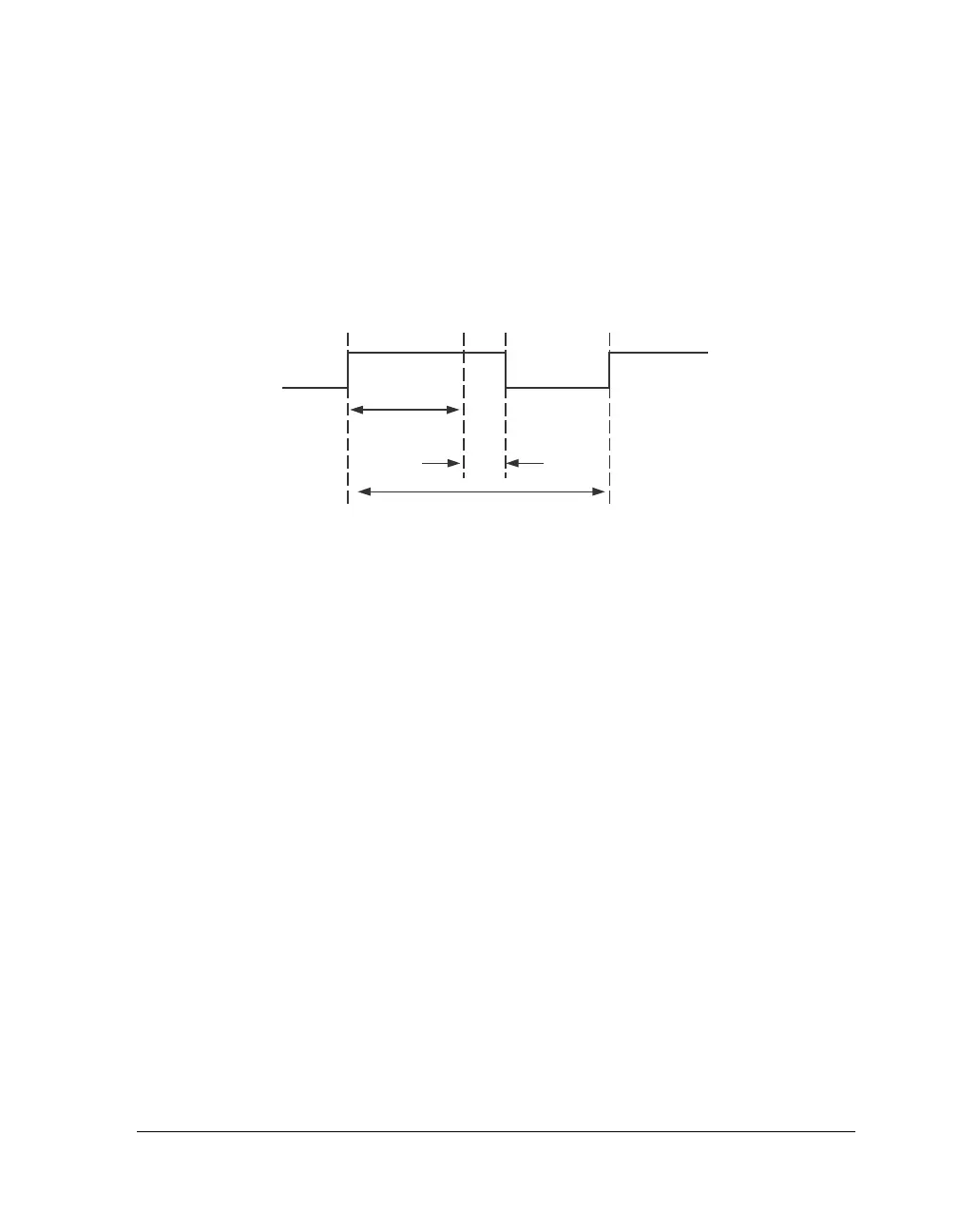
The PWM switching period time for edge aligned mode is:
T
s
= t
PCLK
× PWMPERIOD.
For more information see“Pulse Width Modulation Registers” on
page A-67 .
Center-Aligned Mode
Most of the following description applies to paired mode, but can also be
applied to non-paired mode, the difference being that each of the four
outputs from a PWM group is independent. Within center aligned mode,
shown in Figure 7-6 on page 7-21 there are several options to choose
from.
Center-Aligned Single Update Mode. Duty cycle values are programma-
ble only once per PWM period, so that the resultant PWM patterns are
symmetrical about the mid-point of the PWM period.
Center-Aligned Double Update Mode. Duty cycle values are programma-
ble only twice per PWM period. This second updating of the PWM
registers is implemented at the mid-point of the PWM period, producing
asymmetrical PWM patterns that produce lower harmonic distortion in
two-phase PWM inverters.
Center-Aligned Paired Mode. Generates complementary signals on two
outputs.
Figure 7-5. Edge Aligned PWM Wave with High Polarity

 Loading...

