Register Overview
12-4 ADSP-214xx SHARC Processor Hardware Reference
For information on using the SRU, see “Rules for SRU Connections” on
page 9-20.
Register Overview
The SRC uses five registers to configure and operate the SRC module. For
complete register and bit descriptions, see “Sample Rate Converter Regis-
ters” on page A-184.
Control Registers (SRCCTLx). The SRCCTLx registers enable or disable
the sample rate converters. They also specify the input and output data
format.
Mute Register (SRCMUTE). The
SRCMUTE register controls the connec-
tion of the mute in and mute out signal.
Ratio Registers (SRCRATx). The SRCRATx registers return the sample
ratio between the input and out data stream and mute information (mute
out).
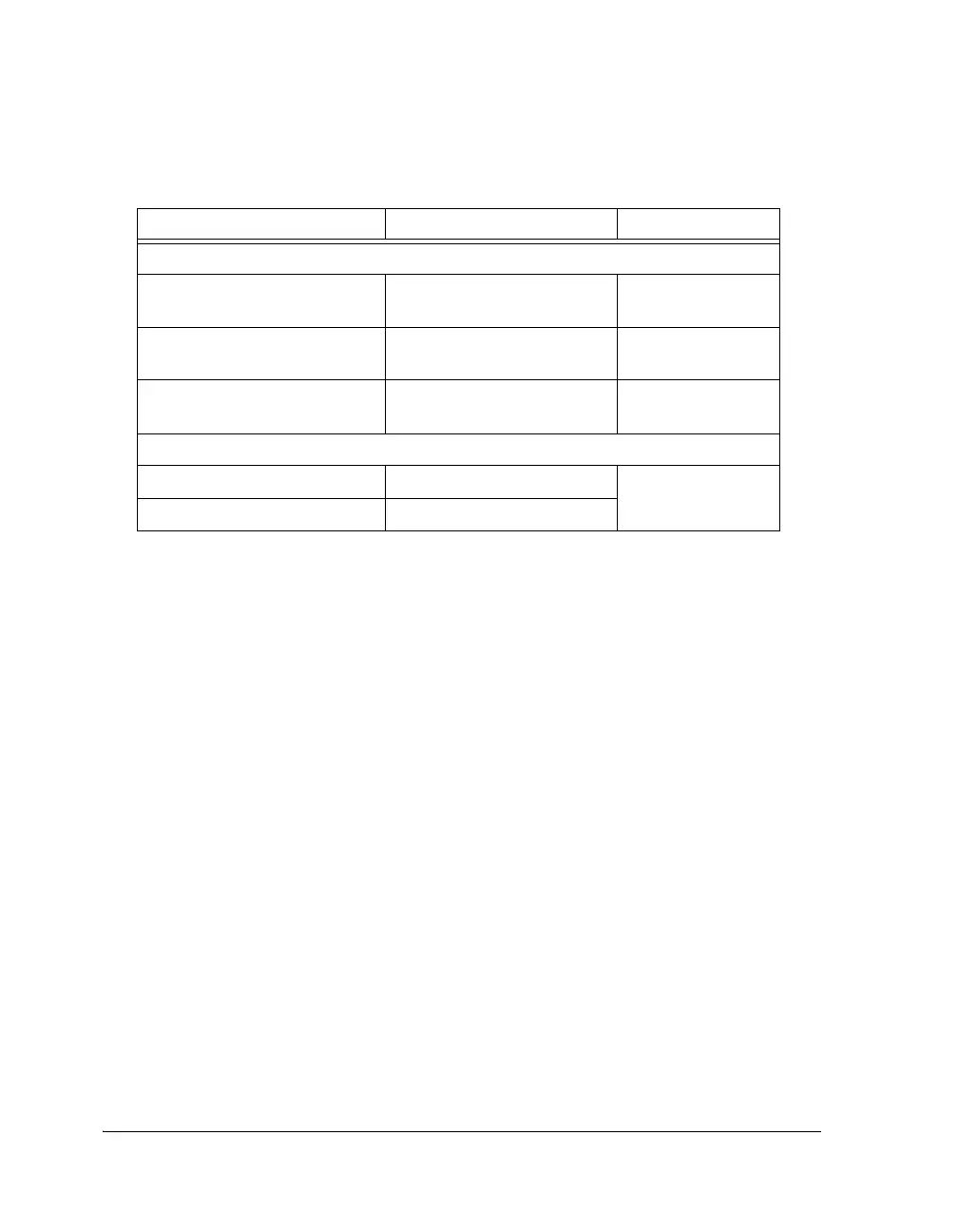
Table 12-3. SRC DAI/SRU Signal Routing
ADSP-214xx Internal Node DAI Connection SRU Register
Inputs
SRC3–0_CLK_IP_I
SRC3–0_CLK_OP_I
Group A SRU_CLK2–1
SRC3–0_FS_IP_I
SRC3–0_FS_OP_I
Group C SRU_FS2–1
SRC3–0_DAT_IP_I
SRC3–0_TDM_OP_I
Group B SRU_DAT3–2
Outputs
SRC3–0_DAT_OP_O Group B, D
SRC3–0_TDM_IP_O Group B

 Loading...

