Peripherals Routed Through the DAI
A-210 ADSP-214xx SHARC Processor Hardware Reference
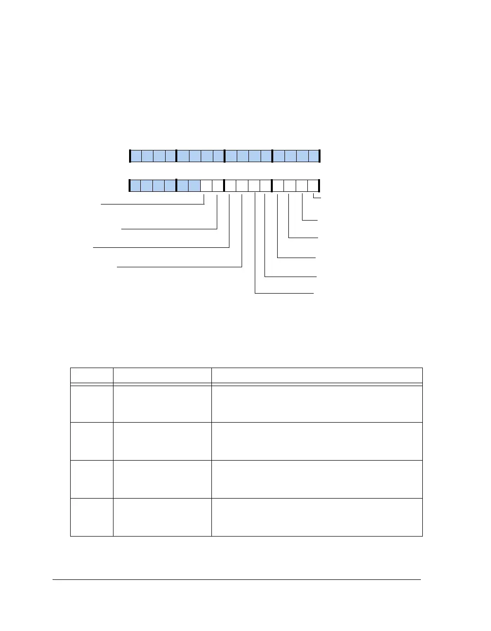
Control Register (RTC_CTL)
This register, shown in Figure A-110 and described in Table A-113 con-
trol interrupt generation for the RTC.
Figure A-110. RTC_CTL Register
Table A-113. RTC_CTL Register Bit Descriptions (RW)
Bit Name Description
0WRDONE_INTENRegister Write Done Interrupt Enable.
0 = Register Write Done interrupt disabled
1 = Register Write Done interrupt enabled
1 SEC_INTEN Seconds Interrupt Enable.
0 = Seconds interrupt disabled
1 = Seconds interrupt enabled
2MIN_INTEN Minutes Interrupt Enable.
0 = Minutes interrupt disabled
1 = Minutes interrupt enabled
3HR_INTEN Hours Interrupt Enable.
0 = Hours interrupt disabled
1 = Hours interrupt enabled
WRDONE_INTEN
Register Write Done
Interrupt Enable
09 837564 2114 12 11 101315
31 302928 27 26 25 24 23 22 21 20 19 18 17 16
SEC_INTEN
Seconds Interrupt Enable
MIN_INTEN
Minutes Interrupt Enable
HR_INTEN
Hours Interrupt Enable
DAY_INTEN
Days Interrupt Enable
1HzCKFAIL_INTEN
1Hz Clock Fail Interrupt Enable
SW_INTEN
Stopwatch Interrupt Enable
DAYALRM_INTEN
Day Alarm Interrupt Enable
ALRM_INTEN
Alarm Interrupt Enable
EMU_INTDIS
Disables RTC interrupts in
emulation mode

 Loading...

