ADSP-214xx SHARC Processor Hardware Reference 20-3
UART Port Controller
SRU Programming
The SRU (signal routing unit) needs to be programmed in order to con-
nect the UART signals to the output pins or connect the output of the
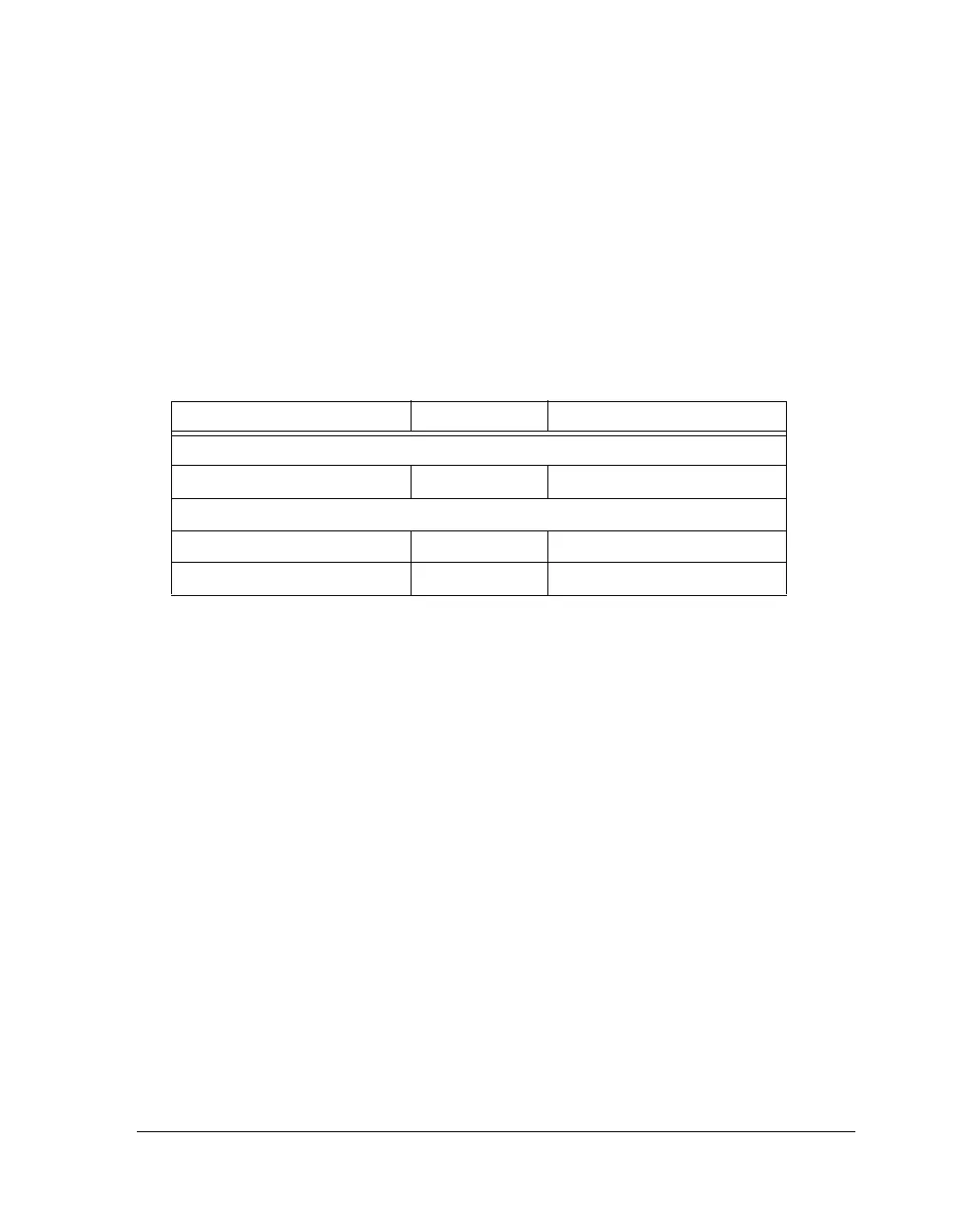
transmitter to the receiver. The UART signals need to be routed as shown
in Table 20-2.
Register Overview
The processor provides a set of PC-style, industry-standard control and
status registers for the UART. These memory-mapped IOP registers are
byte-wide registers that are mapped as half-words with the most signifi-
cant byte zero-filled.
Line Control Register (UARTxLCR). Controls the format of the data
character frames. It selects word length, number of stop bits and parity.
Divisor Latch High/Low Register (UARTxDLL/UARTxDLH). Charac-
terize the UART bit rate. The divisor is split into the divisor latch low
byte (
UARTxDLL) and the divisor latch high byte (UARTxDLH).
Mode Control Register (UARTxMODE). Controls packing and address
modes.
Table 20-2. UART Pin Descriptions
Internal Node DPI Group SRU Register
Input
UART0_RX_I Group A SRU2_INPUT0
Outputs
UART0_TX_O Group A, B
UART0_TX_PBEN_O Group C

 Loading...

