ADSP-214xx SHARC Processor Hardware Reference 15-15
Serial Peripheral Interface Ports
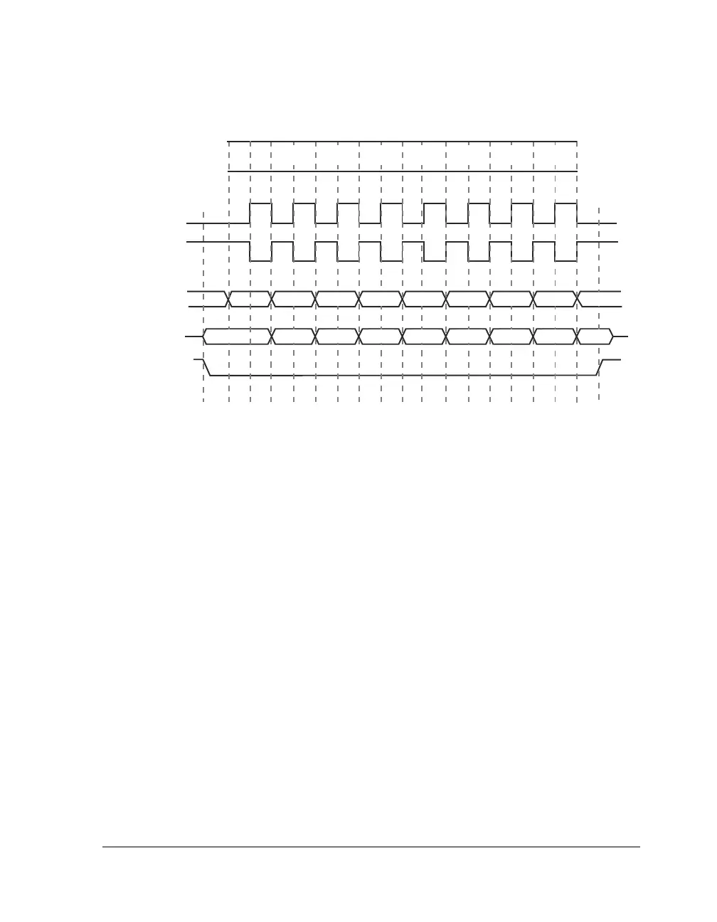
Figure 15-6 shows the SPI transfer protocol for
CPHASE = 1. Note that
SPICLK starts toggling at the beginning of the data transfer where the bit
settings are WL = 0, and MSBF = 1.
Slave Select Outputs
If the SPI is enabled and configured as a master, any of the 14 DPI I/O
pins may be used as slave-select outputs. For each
DSxEN bit which is set in
the SPIFLG register, the corresponding SPI_FLGx_O is configured as a
slave-select output.
For example, if
DS1EN = 1 is set, SPI_FLG1_O is driven as a slave-select. At
the chip-level,
SPI_FLG1_O can be connected to any of the DPI pins
through SRU programming. For those DSxEN bits which are not set, the
corresponding
SPIx_FLGx_PBEN_O is driven low.
The behavior of the
SPI_FLGx output depends on the value of the CPHASE
configuration bit. If CPHASE = 1, all selected outputs may either remain
Figure 15-5. SPI Transfer Protocol for CPHASE = 0
1
CLOCK CYCLE#
SPI_CLK_O
CLKPL=0
(SPI MODE 0)
2 3 4 5 6 7 8
*
6
6 5 4 3
5
4
3 2 1 LSB *
2 1 LSB *
MSB
MSB
* = UNDEFINED
SPI_CLK_O
CLKPL=1
(SPI MODE 2)
SPI_MOSI_O
FROM MASTER
SPI_MISO_I
FROM SLAVE
SPI_FLG_I
FROM MASTER

 Loading...

