Peripherals Routed Through the DPI
A-264 ADSP-214xx SHARC Processor Hardware Reference
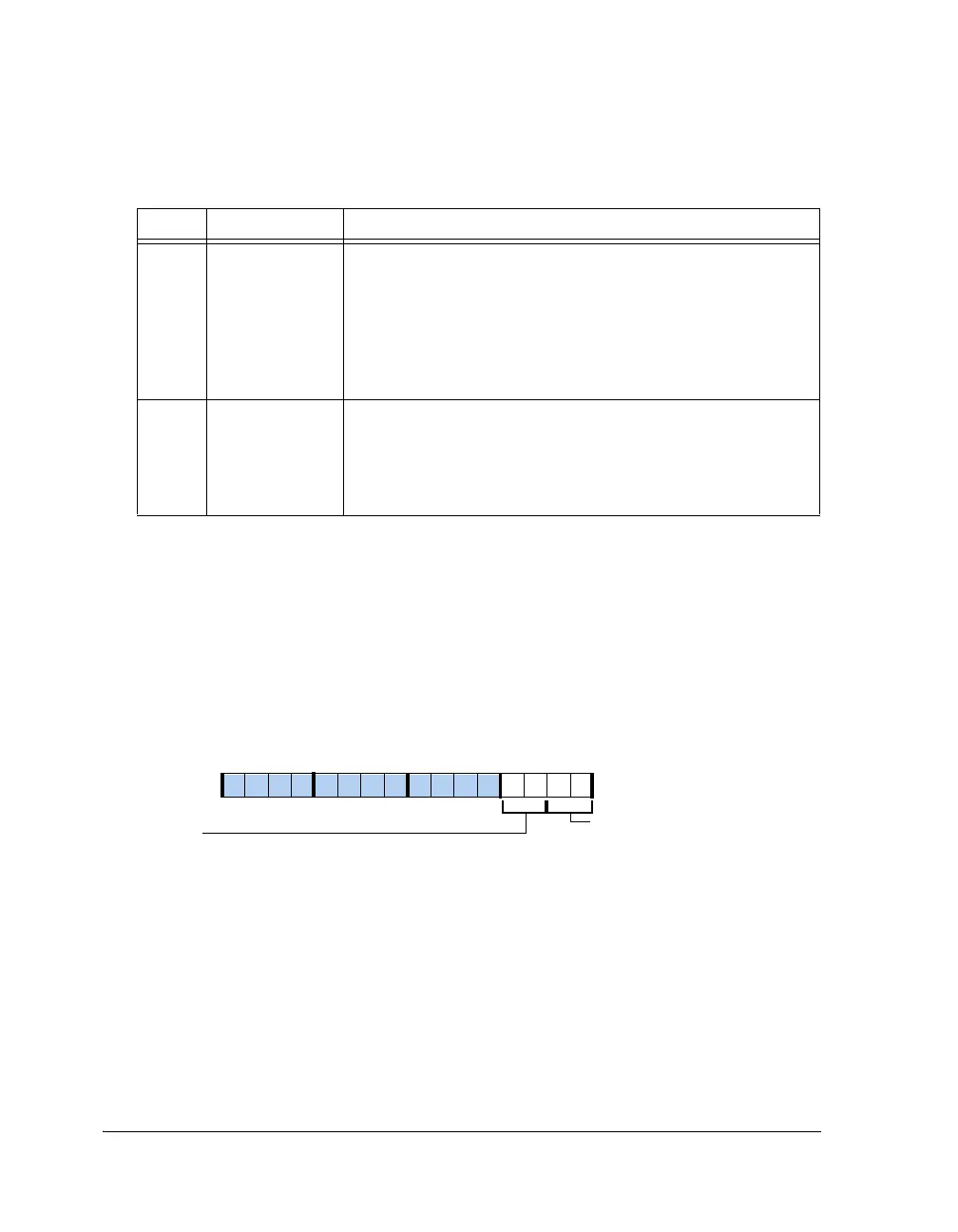
FIFO Status Register (TWIFIFOSTAT)
The fields in the TWI FIFO status register (
TWIFIFOSTAT, shown in
Figure A-152 and described in Table A-143) indicate the state of the
FIFO buffers’ receive and transmit contents. The FIFO buffers do not dis-
criminate between master data and slave data. By using the status and
control bits provided, the FIFO can be managed to allow simultaneous
master and slave operation.
3 TWIRXINT2 Receive Buffer Interrupt Length. Determines the rate at which
receive buffer interrupts are generated. Interrupts may be generated
with each byte received or after two bytes are received.
0 = An interrupt (TWIRXINT) is set when TWIRXS indicates one
or two bytes in the FIFO are full (01 or 11).
1 = An interrupt (TWIRXINT) is set when TWIRXS indicates two
bytes in the FIFO are full (11).
4 TWIBHD Receive Buffer Hang Disable.
0 = Read of FIFO happens only when Rx FIFO has a valid byte.
Write of FIFO happens only when Tx FIFO has at least one empty
space.
1 = Read/write happens irrespective of FIFO status
Figure A-152. TWIFIFOSTAT Register
Table A-142. TWIFIFOCTL Register Bit Descriptions (RW) (Cont’d)
Bit Name Description
TWITXS (1–0)
TWIRXS (3–2)
Receive FIFO Status
Transmit FIFO Status
09 837564 2114 12 11 101315

 Loading...

