ADSP-214xx SHARC Processor Hardware Reference A-215
Registers Reference
register. The day interrupt occurs whenever the day, hour, minute, and
second fields first match those of the RTC status register.
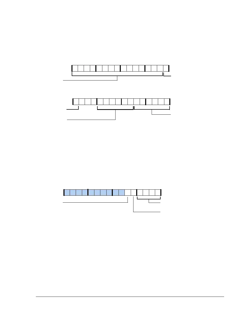
Initialization Register (RTC_INIT)
This register, shown in Figure A-115 and described in Table A-115, pro-
vides the calibration function, powers down the unit, and grounds these
buses.
Figure A-114. RTC Alarm Register (RW)
Figure A-115. RTC_INIT Register
09 837564 2114 12 11 101315
31 302928 27 26 25 24 23 22 21 20 19 18 17 16
HOUR (16-12)
MINUTE (11-6)
Alarm Hour 0–23
Alarm Minute 0–59
DAY (31-17)
Alarm Day 0–32767
SECOND (5-0)
Alarm Second 0–59
HOUR (16-12) (Con’t)
Alarm Hour 0–23
CALIB (3–0)
Time Calibration
RTCPDN
Power Down
RTC_READEN
Output Bus
Enable
09 837564 2114 12 11 101315

 Loading...

