Processor Reset
23-6 ADSP-214xx SHARC Processor Hardware Reference
System Considerations
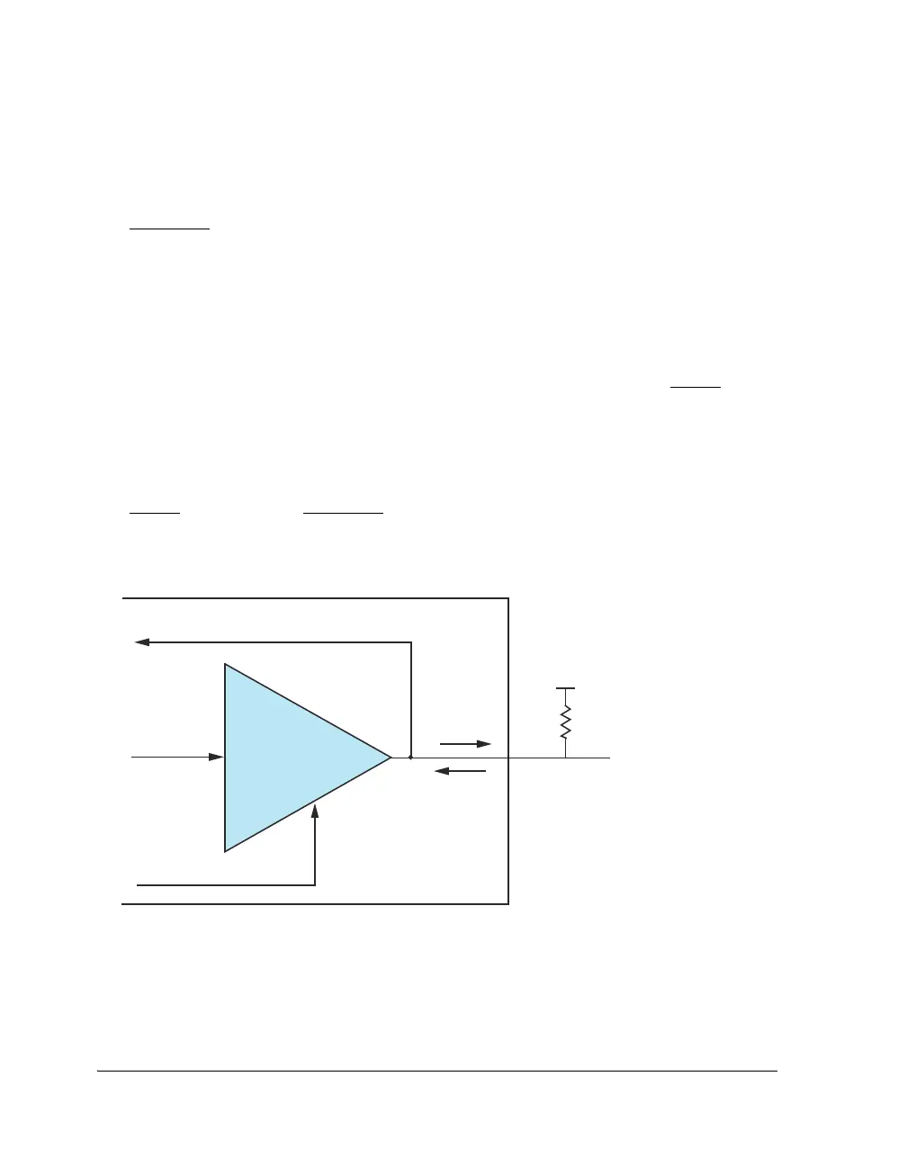
It is important that an external 10 kΩ pull-up resistor is placed on the
RESETOUT pin if it is intended to be used as an input for initiating a run-
ning reset as shown in Figure 23-1.
It is also extremely important to ensure that an external device,
such as a micro controller, does not drive this signal during or after
coming out of a power-on or hard-reset.
Figure 23-1 shows the active state of the pin during and after RESET. The
processor is actively driving this pin as an output. If the system uses an
external host or micro controller to control running reset, ensure that the
external device waits until the processor driver has been internally disabled
(by writing to the RUNRSTCTL register) before actively driving this signal at
RESET. Connect the RESETOUT pin to an open-drain pin on the host side, or
use an external three-state buffer.
Figure 23-1. RESETOUT Pin Multiplexed with RUNRSTIN
Ensure that host processor
has an open-drain output
and is not actively driving
this pin during or after RESET
PAD
DRIVER
RESETOUT
RUNRSTIN
V
DD
10 k:
ADSP-214xx
RUNNING RESET
CONTROL

 Loading...

