ADSP-214xx SHARC Processor Hardware Reference 3-27
External Port
For two-banked SDRAMs, connect BA with A17. Note that page
interleaving is not supported with 2 bank devices.
The mapping of the addresses depends on the row address width
(SDRAW), column address width (SDCAW), and the address mode bit
(SDADDRMODE) setting.
Address Width Settings
Address width settings can be configured as shown in Table 3-11.
Number of Internal Banks. The controller assumes the SDRAM is com-
prised of four bank devices. However, SDRAM can use two bank devices
by not connecting the
ADDR18 pin.
Figure 3-7. Core Address Mapping—Page and Bank Interleaving
Table 3-6. External Memory Address Bank Decoding
IA[27] IA[26] External Bank
00Bank 0
01Bank 1
10Bank 2
11Bank 3
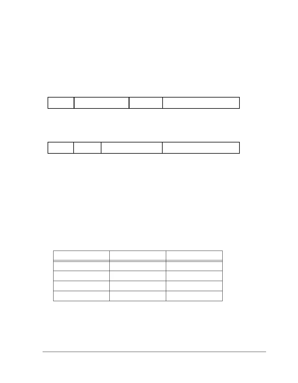
31 0
Unused
Bank
Column AddressRow Address
Address
31 0
Unused
Bank
Column Address
Row Address
Address
CORE ADDRESS MAPPING, TO ROW, COLUMN ADDRESSES (Bank Interleaving, SDADDRMODE=0)
CORE ADDRESS MAPPING, TO ROW, COLUMN ADDRESSES (Page Interleaving, SDADDRMODE=1)

 Loading...

