ADSP-214xx SHARC Processor Hardware Reference 23-29
System Design
Flag pins (FLG3-0) are connected as input after reset.
If more than four flags are required, they can multiplexed using the exter-
nal port pins in the SYSCTL register or the DPI pins in the DPI registers.
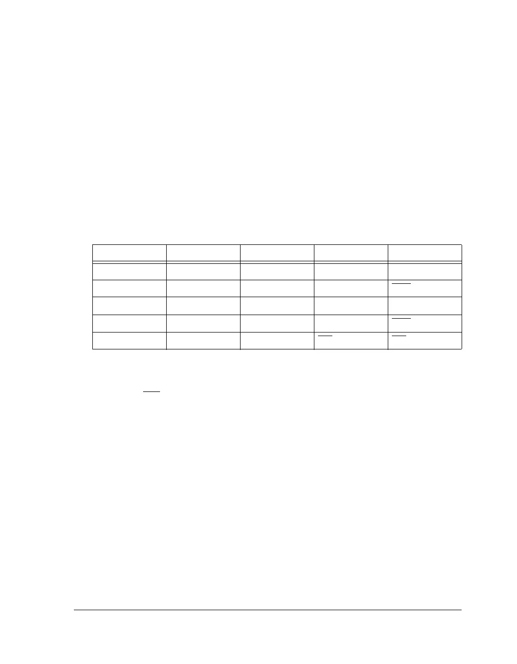
For a detailed flag description refer to the SHARC Processor Programming
Reference. Table 23-14 provides information on FLAG function based on
the settings of the memory select enable, the flag timer expired and the
FLAG2 interrupt bits in the system control register.
Backward Compatibility
The FLAG/IRQ (0, 1, 2, 3) pins retain their old functionality and program-
ming. No changes are required for old programs. The select lines for
multiplexes are controlled by the SYSCTL register. For more information,
see “System Control Register (SYSCTL)” on page A-4.
External Port Pin Multiplexing
Various peripherals use the external port for off-chip communication.
These peripherals use multiplexed I/O pins and have the (functions)
shown:
• External Port (AMI/SDRAM/DDR2)
• PDAP (input)
Table 23-14. Flag 3–2 Truth Table (SYSCTL Register)
MSEN Bit TMREXPEN Bit IRQ2EN Bit FLAG3 Function FLAG2 Function
000
FLAG3 FLAG2
001FLAG3 IRQ2
010TMREXP FLAG2
011TMREXP IRQ2
100MS3 MS2

 Loading...

