ADSP-214xx SHARC Processor Hardware Reference A-65
Registers Reference
Status Registers (LSTATx)
Figure A-29 and Table A-34 describe the bit fields within this register.
9LRRQ_MSKLink Port Receive Request Mask.
0 = Mask
1 = Unmask
10 DMACH_
IRPT_MSK
DMA Channel Count Interrupt Mask. Must be set to generate inter-
rupt if DMA count is zero and is compatible with traditional SHARC
processors.
0 = Mask
1 = Unmask
11 LPIT_MASK Invalid Transmit Interrupt Mask.
0 = Mask
1 = Unmask
12 EXTTXFR_
DONE_
MSK
External Transfer Done Interrupt Mask. Valid for core and DMA
accesses. If set interrupt is generated when the FIFO is empty. Note if
bit 10 is also set for DMA, two interrupts are generated, one for
DMA count=0 and one for FIFO empty.
0 = Mask
1 = Unmask
31–13 Reserved
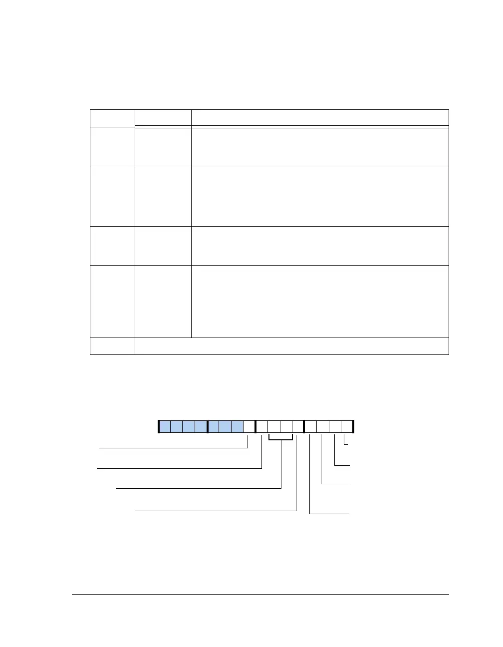
Figure A-29. LSTATx Register
Table A-33. LCTLx Register Bit Descriptions (RW) (Cont’d)
Bit Name Description
LTRQ
Link Port Rx Request Status
Link Port Tx Request Status
DMACH_IRPT
DMA Channel Interrupt
LRRQ
LPIT
Link Port Invalid Tx
Interrupt
EXTTXFR_DONE
External Transfer Done
Interrupt
FFST (6–5)
Link Buffer Status
LPBS
Link Port Bus Status (Tx)
LERR
Link Buffer Rx Pack Error Status
09 837564 2114 12 11 101315

 Loading...

