ADSP-214xx SHARC Processor Hardware Reference A-111
Registers Reference
Channel x Current Buffer Configuration Registers
(MLB_CCBCRx)
These read-only registers, described in Table A-69, allow software to mon-
itor the address pointer and buffer length of the current DMA buffer in
internal memory when the logical channel is configured in DMA mode.
When configured in I/O mode, this register implements the Rx data
buffer. The definition of the bit fields in this register vary depending on
the selected channel type.
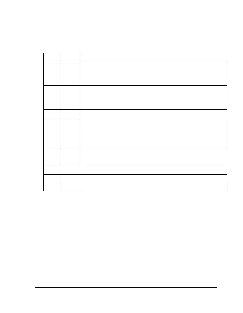
10 STS10
(DMA)
Previous Buffer Done. Indicates that the last quadlet of the Previous Buffer has
been successfully transmitted or received. The setting of this bit generates a mask-
able channel interrupt to system software. This bit is valid for all channel types.
Reserved in I/O mode.
11 STS11
(DMA)
Previous Buffer Start. Indicates the first quadlet of the Previous Buffer has been
successfully transmitted or received. The setting of this bit generates a maskable
channel interrupt to system software. This bit is valid for all channel types.
Reserved in I/O mode.
15–12 Reserved
16
(RW)
RDY Next Buffer Ready (DMA Mode). This bit is reserved for I/O mode.
0 = Next buffer ready for ping-pong DMA. Hardware clears this bit after the buf-
fer begins to be processed.
1 = Next buffer ready for circular buffer DMA. Software should clear this bit only
when buffer processing needs to be stopped.
17
(RW)
GIRB Reserved = For Synchronous Channels.
0 = Generate isochronous receive break for isochronous channels.
1 = Generate break for asynchronous and control channels.
29–18 Reserved
30 BF Channel x Buffer Full. When set, buffer is full.
31 BM Channel x Buffer Empty. When set, buffer is empty.
Table A-68. MLB_CSCRx Register Description (RO) (Cont’d)
Bit Name Description

 Loading...

