ADSP-214xx SHARC Processor Hardware Reference A-51
Registers Reference
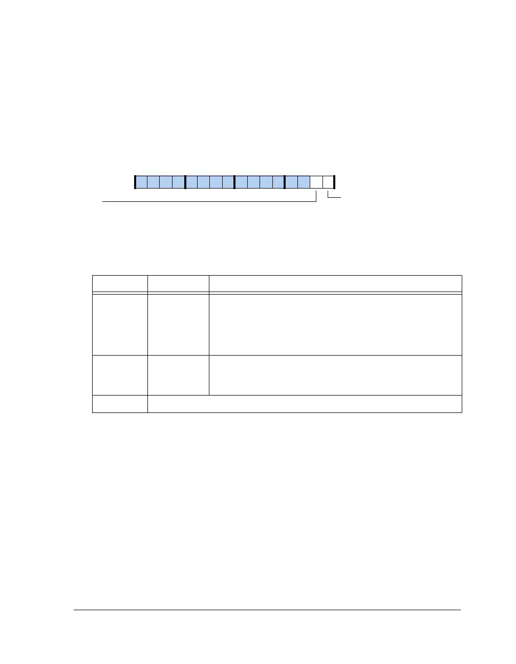
AMI Status Register (AMISTAT)
This 32-bit register provides status information for the AMI interface and
can be read at any time. This register is shown in Figure A-22 and
described in Table A-27.
SDRAM Registers
This section provides complete descriptions of the SDRAM controller’s
memory-mapped registers for SDRAM programming.
Control Register (SDCTL)
The SDRAM memory control register includes all programmable parame-
ters associated with the SDRAM access timing and configuration. This
32-bit register is shown in Figure A-23 and described in Table A-28.
Figure A-22. AMISTAT Register
Table A-27. AMISTAT Register Bit Descriptions (RO)
Bit Name Description
0AMIMSAMI External Bus Master.
0 = SDRAM Controller controls the external bus
1 = AMI controls the external bus (default)
For ADSP-2146x processors bit 0 is always (=1) since the DDR2
and AMI are not shared
1AMISExternal Interface Status.
0 = AMI interface idle
1 = AMI access pending
15–2 Reserved
AMIS
External Interface Status
09 837564 2114 12 11 101315
AMIMS
External Bus Master

 Loading...

