Operation Modes
10-30 ADSP-214xx SHARC Processor Hardware Reference
I
2
S Mode
The following sections provide information on using I
2
S mode.
Master Serial Clock and Frame Sync Rates
The serial clock rate (CLKDIV value) for internal clocks can be set using a
bit field in the DIVx register and the frame sync rate for internal frame sync
can be set using the FSDIV bit field in the DIVx register based on the MSTR
bit setting.
The transmitter sends the MSB of the next word in the same clock cycle as
the word select (SPORTx_FS) signal changes. To transmit or receive words
continuously in I
2
S mode, load the FSDIV register with SLEN–1. For exam-
ple, for 8-bit data words set
FSDIV = 7.
Timing Control Bits
Several bits in the SPCTLx register enable and configure I
2
S mode
operation:
• Master Mode Clock and Frame Sync (
MSTR)
• Sampling Edges Frame Sync/Data (
CKRE)
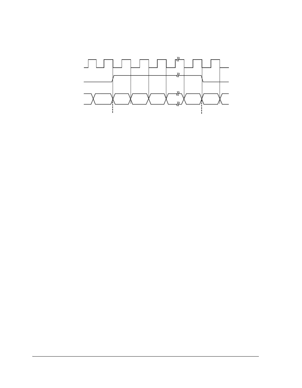
Figure 10-6. Word Select Timing in Left-Justified Mode
SPORTx_CLK
SPORTx_FS/WS
LEFT-JUSTIFIED SAMPLE
PAIR MODE
SPORTx_DA/DB DATA
MSB
n
SAMPLE n
LEFT CHANNEL
SAMPLE n+1
LSB
n
MSB
n+1
SAMPLE n
-
1
LSB
n-1

 Loading...

